

Drawings and documents
National Archives restored drawings: drawing
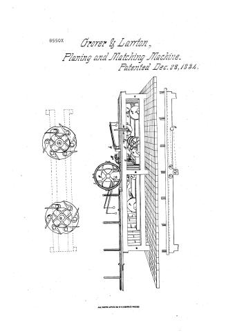
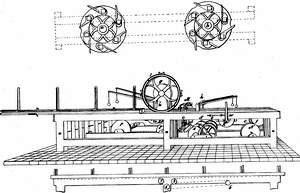
Grover and Lawton's Patent Drawing for a Planing and Matching Machine

National Archives, Restored Patent Drawings (Record Group 241) · Full-size scan at the National Archives · Catalog record
Show the text on the drawing Hide (60 words)
Words on the drawing as machine-read by the National Archives; not checked. Useful mainly for searching.
$250 / December 23d 1834 / Res. may 8.1851. 8 / Grover & Lawtons Planing and M Matching Machine. / 144 WOOD-WORKING MACHINES. / S. / Planing and Matching. / one fourth full size / Sexional drawings of / matching wheels. / CAL CAUSATION / 8550-X / DIVISION. / Patented Dec.23.1337 / Patented Dec. 23-1834- / #.4 / 11 / Carriage / И. / iP / Carriage / 6' / Sexional drawing of Carriage
USPTO scan
The patent as scanned by the USPTO
-
 Page 1
-
 Page 2
-
 Page 3
-
 Page 4
-
 Page 5
-
 Page 6


U.S. Patent and Trademark Office · Google Patents
Show the transcription Hide (1,443 words)
Machine transcription (LightOnOCR) of the pages as scanned by the USPTO, most of them the handwritten copies made when the records were restored after the 1836 fire. Not checked; it can misread handwriting, so compare it with the scan.
Page 1.
8550X
Grover & Larron,
Planing and Matching Machine.
Patented Dec. 23, 1834.

ANL PHOTO-LITHO. CO. N.Y. (OSBORNE'S PROCESS)
Page 2.
302
Zadock B. Grover & David Lawton, Springwater, N.Y.
Patent issued December 23, 1834
The Schedule referred to in these Letters Patent and making part of the same containing a description in the words of the said Zadock B. Grover and David Lawton, themselves of their Improvement in a Machine for planing and matching boards.
To all to whom these presents shall come
Be it known that we, Zadock B. Grover & David Lawton of the Town of Springwater County of Livingston and State of New York have invented a new & useful Improvement for planing and matching boards denominated a Planing & Matching Machine; and that the following is a full & exact description of the Construction and operation of the said machine as invented by us.
The principal executions are three wheels: One denominated the planing wheel, and two the matching or tonguing & grooving wheels. The planing wheel has attached to its outer edge or rim, four hooked knives equidistant from each other, and fastened by plates screwed upon them. These knives operate before the planes to rough hew and equalize the thickness of the board. Between and immediately within the sweep of these knives, and at equal distance from each, are four irons placed in throats, so as to bring them in contact with the board to be planed, at the side of the wheel. These plates are fastened to the oblique sides of the throats with screws which are moved in slots, as occasion requires, for the purpose of bringing them upon a plane with a circular form—never immediately within their sweep. Another form of applying the planes to the wheel is as follows. The plane
Page 3.
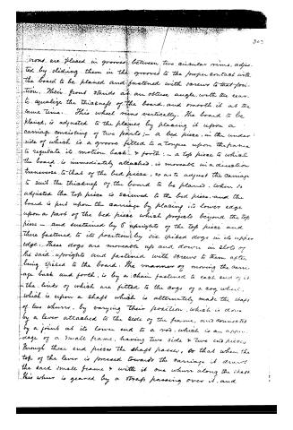
Irons are placed in grooves between two circular rims, adjusted by sliding them in the grooves to the proper contact with the board to be planed and fastened with screws to that position. Their front stands at an obtuse angle, with the rear to equalize the thickness of the board, and smooth it at the same time. This wheel runs vertically. The board to be planed is adjusted to the planes by placing it upon a carriage consisting of two parts;—a bed piece, in the under side of which is a groove fitted to a tongue upon the frame to regulate its motion back & forth;—a top piece to which the board is immediately attached, is movable in a direction transverse to that of the bed piece, so as to adjust the carriage to suit the thickness of the board to be planed. When so adjusted the top piece is screwed to the bed piece, and the board is put upon the carriage by placing its lower edge upon a part of the bed piece which projects beyond the top piece—and sustained by 6 uprights of the top piece and there fastened to its position by six spiked dogs in its upper edge. These dogs are movable up and down in slots of the said uprights and fastened with screws to them after being spiked to the board. The manner of moving the carriage back and forth, is by a chain fastened to each end of it—the links of which are fitted to the cogs of a cog wheel, which is upon a shaft which is alternately made the shaft of two whorrs, by varying their position, which is done by a lever attached to the side of the frame, and connected by a joint at its lower end to a rod, which is an appendage of a small frame, having two side & two end pieces through these end pieces the shaft passes, so that when the top of the lever is pressed towards the carriage it draws the said small frame & with it one whorl along the shaft. This whorl is geared by a strap passing over it, and
Page 4.
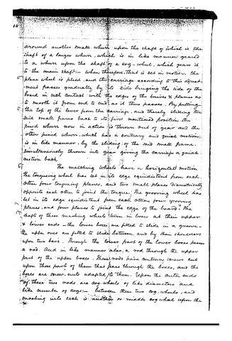
around another small whurr upon the shaft of which is the shaft of a larger whurr, which is in like manner geared to a whurr upon the shaft of a cog-wheel, which gears it to the main shaft:— when therefore, that is set in motion, the plane wheel is plied, and the carriage according to this adjustment passes gradually by its side bringing the side of the board in such contact with the edges of the knives & planes as to smooth it from end to end, as it thus passes. By pulling the top of the lever from the carriage, and thereby sliding the said small frame back to its first mentioned position, the pinion whurr now in action is thrown out of gear and the other pinion whurr, which has a contrary and quick motion, is in like manner, by the sliding of the said small frame, simultaneously thrown into gear giving the carriage a quick motion back.
The matching wheels have a horizontal motion. The tonguing wheel has set in its edge equidistant from each other four tonguing planes, and two small planes diametrically opposite each other to join the tongue. The grooving wheel has set in its edge equidistant from each other four grooving planes, and four planes to join the edge of the board. The shafts of these matching wheels turn in boxes at their upper & lower ends—the lower boxes are fitted to slide in a groove—the upper ones are fitted to slide between, and by their shoulders upon two bars. Through the lower part of the lower boxes passes a rod. And in like manner also, a rod through the upper part of the upper boxes. These rods have contrary screws cut upon those parts of them that pass through the boxes, and the boxes are screw-nuts adapted to them. Upon the outer ends of these two rods are cog-wheels of like diameters and like number of cogs:— between these two cog-wheels, and meshing into each is another or middle cog wheel upon the
Page 5.
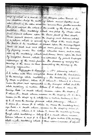
shaft of which is a crank, which therefore, when turned in one direction, brings the matching wheels nearer together and when turned in the other direction removes them farther asunder. This is to adjust the wheels to the width of the board to be matched. These matching wheels are held by straps which pass around whorrs upon the lower parts of their shafts, thence around drums, upon the shaft of, and between which is a whorrr which is geared by a strap to the main shaft. The board to be matched is placed upon the carriage dogged down at each end and stayed more firmly to the carriage by passing under two rollers situated near, and on each side of the matching wheels, and borne down upon the board by weighted levers, which are attached by joints to upright appendages of the main frame. The process of moving this carriage is the same as that described of the carriage of the planing apparatus.
References to Drawings - No 1 planing wheel - h.h rollers with their weighted levers to hold the board firm to the carriage while matching - The machinery is geared by straps as follows - Whorrr 2, to whorrr 3 - whorrr 4 to a drum under the floor, not represented in the draught which puts the whole machinery in motion. Whorrr 5 to whorrr k runs the carriage back - a small whorrr, unseen, upon the shaft of 5 to whorrr N, - small whorrr, unseen, on the shaft of N, to whorrr, unseen, on the shaft of k, which has a motion contrary to that of k, to move the carriage forward while planing - Whorrr o, to drum p, - drum p, to whorrr u, runs the matching carriage back - a small whorrr, unseen on the shaft of drum p, to whorrr, r - whorrr, s, to whorrr, t, runs the matching carriage through, while matching - Whorrr q, to a small whorrr, unseen, between whorrrs e, and f to C and D, give motion to the matching wheel, - M, matching wheels & their appendances, to adjust
Page 6.
them to the width of board to be matched — a lever which changes the position of the wheels which move the carriage back and forth.
Witnesses:
Thomas C. Grover
Rufus G. Clark
Jadock B. Grover
David Lawton
(Recorded anew May 6, 1851)
1660
Published accounts: journal notice
Notice in the monthly list of patents
Journal of the Franklin Institute, new ser., vol. 15 (1835), p. 144 · View the page
620. Planing and grooving.-Z. B. Grover and D. Lawton, Springwater, New York, •
Published accounts: journal notice
Notice in the monthly list of patents, with remarks
Journal of the Franklin Institute, new ser., vol. 16 (1835), p. 33 · View the page
50. For a Machine for Planing and Matching Boards; Zadock B. Grover, and David Lampton, Springwater, Livingston county, New York, December 23.
Remarks. This planing and tonguing and grooving apparatus is not as clearly described as might be desired, although the specification is of sufficient length, and the drawings are well executed; it appears plainly, however, that it is similar in principle to Woodworth's machine, although differing from it in its minor arrangements. What the patentees have invented, they do not tell us, there not being any thing in the nature of a claim.
DATAMP: illustration
Illustrations from DATAMP

DATAMP (Directory of American Tool and Machinery Patents), via the Internet Archive · Archived DATAMP page
About this record
- Patentee
- DATAMP
- Date
- the Name and Date index of patents, DATAMP, USPTO records
- Invention
- DATAMP
- Listed in
- the Name and Date index of patents, DATAMP, USPTO records, Jim Shaw's X-patent list, the Journal of the Franklin Institute, Burke's List of Patents (1847)
- Burke's 1847 Patent Office list gives the same patent.