

Drawings and documents
National Archives restored drawings: drawing
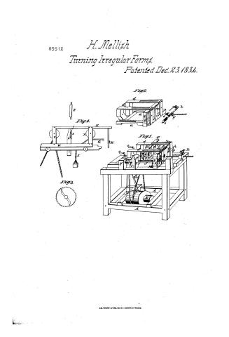
Henry Mellish's Patent Drawing for a Machine for Turning Lasts, Boot-trees, Spokes, and Other Articles That Might be Turned By a Pattern

National Archives, Restored Patent Drawings (Record Group 241) · Full-size scan at the National Archives · Catalog record
Show the text on the drawing Hide (58 words)
Words on the drawing as machine-read by the National Archives; not checked. Useful mainly for searching.
142 WOOD WORKING. / 1. LATHES. / [172] TurningIrregular Forms / $2- / CLASSIFICATION / 8551- / DIVISION. / HENRY MELLISH'S / Machine for Turning Lasts, Boottrees, Spokes,and other articles that may be Jurned / By a Patterny. / Patented 23 "D ecember 1834. / FG.IL. / INC / al / YL / 1H / 72 / IK / II / FIG.IN.
USPTO scan
The patent as scanned by the USPTO
-
 Page 1
-
 Page 2
-
 Page 3
-
 Page 4
-
 Page 5


U.S. Patent and Trademark Office · Google Patents
Show the transcription Hide (1,827 words)
Machine transcription (LightOnOCR) of the pages as scanned by the USPTO, most of them the handwritten copies made when the records were restored after the 1836 fire. Not checked; it can misread handwriting, so compare it with the scan.
Page 1.
8551X
H. Mellish
Turning Irregular Forms.
Patented Dec. 23, 1834.
Fig. 2.
Fig. 4.
Fig. 1.
Fig. 5.
AM. PHOTO-LITHG. CO. N.Y. (OSBORNE'S PROCESS)
Page 2.
8551X Dec. 23, 1874
Henry Mellish of Walpole, New Hampshire
Letters Patent
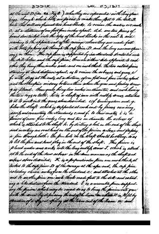
The schedule referred to in these Letters Patent and making part of the same containing a description in the words of the said Henry Mellish himself of his improvement being a machine for turning Saws, Bolt trees, Spokes and other articles that may be turned by a pattern.
To all to whom these presents shall come: Be it known that I Henry Mellish of Walpole, in the County of Cheshire and State of New Hampshire, have invented a new and useful improvement in the useful arts being a machine for turning Saws, Bolt trees, Spokes and other articles that may be turned by a pattern called Mellish’s pattern guiding turning lathe, and that the following is a full and exact description of the construction and operation of the same as invented and improved by me, reference being had to the annexed drawings.
Fig. 1, is a perspective view of the machine. A.B. The frame is constructed by nailing and tenoning together four posts, eight rails, and two cross rails to support the main cylinder, and the rail a to support the quage foot and finisher. The whole being made of timber three inches and a half square and forming a frame three feet three inches long, and three feet and two inches wide, and two feet and seven inches high. The rail B being its whole thickness above the seat of the frame. C. is a carriage running on tracks in the top end rails of the frame, and is three feet seven inches long by two feet seven inches wide. The inside edges corners of the long rails of this carriage are halved away so as to form a ledge for the carriage D to slide on. D is a carriage containing the cutters and dogs, and gears to hold and turn the pattern and timber to be worked. The width of this carriage is such as to fit into the carriage C in which it slides, the length one foot nine inches and one half, and the height one foot two inches. The Sills are made of timber three inches square being framed together and made fast at the end D with bolts, the side sills having one half their thickness cut away at the under sides to within two inches of the ends, and
Page 3.
at the end D (see Fig. 2) when they are represented with long openings, through which bolts are passed to make them fast to the sill B. Into this sill are framed two head blocks, to receive the centres or cranks C, at a distance of one foot four inches apart. d.d. are two pieces of board dovetailed into the tops of the head blocks in the sill B, and reaching to the opposite end of the carriage where they are made fast with bolts passing up through the cap piece D, and the long narrow openings in them. This cap piece is supported by six standards dovetailed into the sill below and the cap piece. There on either side opposite to each other they being three inches wide and one inch thick. The two outside pairs standing at such distance apart, as to receive the arbors and gears, e.f. with dogs at the ends, at a distance of one foot and four inches apart and the other pair midway between them where the gear and feeding screw g is placed. These gears being two inches in diameter, and each having thirteen cogs or teeth. h is a shaft of iron with endless screws attached to it to work into the gears above described. e.f. turning above and g. below the shaft which is supported at each end by pieces running across and connecting the standards c. and f. to their mates; i is a pinion of iron, five inches long and two in diameter, the arbor of which is attached to the shaft h. by drilling a hole in the end of the shaft and inserting an oval head on the end of the pinion arbor and passing a pin through both: the pin hole in the shaft should be oblong, so as to let the pin and head play in the end of the shaft. This pinion is placed under and works into the long endless screw J, which is attached to the end of the saw arbor in the same manner as the shaft and arbor above described. K is a perpendicular piece one inch thick, at tacked to the cap piece D of the carriage at the after end. The cap piece extending eleven inches from the standard c. and attached at the other end to another piece one inch thick made fast to the sill and extending a like distance from the standard. L is a movable piece supporting the pinion which may be raised so as to bring the pinion into gear with the screw by depressing the end of the beam on which it is, kept by operation of a spring at the lower end of the beam N. and
Page 4.
8551X Dec 23, 1834
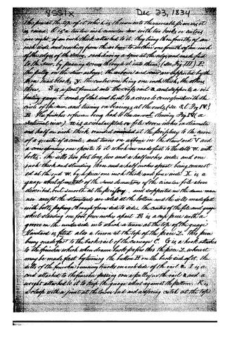
the fin at the top of it which is thrown into the movable piece as it is raised. O is a twelve inch circular saw with two hooks or cutters one eight of an inch thick attached to it, they being three fourths of an inch wide and reaching from the arbor to within one fourth of an inch of the edges of the slats, each having a spur at the edge and made fast to the saw, by passing screws through it into them, (see Fig III) P, the pully on the saw arbor, the arbor and saw are supported by the three lead blocks, S, the centre one being one inch thick, the others three. S is a post formed into the cross rail & and supports a vibrating gauge t made of steel and bent to a curve to correspond with the circle of the saw, and turning on bearings at the ends, (see S. t. Fig IV.) B The finisher reference being had to the anwort drawing Fig IV (a sectional view) W is a circular plate or file seven inches in diameter and half an inch thick, rounded rounded at the periphery to the curve of a quarter of a circle, and turns on arbors in the standard V and a corresponding one opposite to it which are made fast to the sills W, with bolts. The sills two feet long, two and a half inches wide, and one inch thick and standing three and a half inches apart, being connected at the end W, by a piece one inch thick and four wide X is a gauge wheel of metal of the same dimensions of the circular file above described, but smooth at the periphery, and supported in the same manner except the standards are solid at the bottom and the sills made fast with bolts passing through from side to side. The centre of the file and gauge wheel standing one foot four inches apart B is a cap piece with a groove in the underside into which a tenon at the top of the gauge standard is fitted also a tenon at the top of the piece Z. This piece being made fast to the back rail of the carriage C. G is a hook attached to the finisher which when drawn back passes thro the piece Z, where it may be made fast by turning the button H on the back side of it. The sills of the finisher running tracks on each side of the rail &. I is a cord attached to the finisher passing over a pulley in the rail & and a weight attached to it to keep the gauge wheel against the pattern. K is a latch with a joint at the lower end and a spring catch at the top.
Page 5.
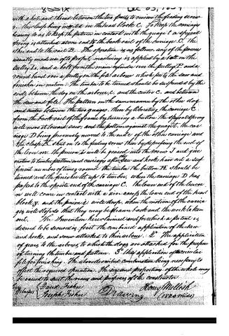
with a hole and thread between the two parts to receive the feeding screw, this clasp being inserted in the head block C. To keep the carriage bearing so as to keep the pattern in contact with the quagat a spiral spring is attached at one end to the back rail of the carriage C. The other end to the rail B. The operation is as follows. Any of the powers usually made use of to propel machinery is applied by a belt on the pulley L, and a belt from the main cylinder over the pulley P, and a round band over a pulley on the file arbor, which puts the saw and finisher in motion. The timber to be turned should be suspended by the ends between the dog in the arbor, C, and the centre C, and between the saw and file. The pattern in the same manner by the other dog and centre between the two quagats. Then by elevating the carriage C from the back rail of the frame by turning a button the spiral spring will move it toward saw, and the pattern against the quagat. The carriage D being previously moved to the end of the other carriage and the clasp K shut on to the feeding screw then by depressing the end of the lever M, the pinion is will be geared into the screw J and give motion to timber pattern and carriage after saw and hooks have cut a sufficient number of times round the timber the button H should be turned and the finisher let up to timber, when the carriage D has passed to the opposite end of the carriage C. The lower end of the lever M will come in contact with a pin across the lower end of the head block Y, and the pinion is will drop, when the motion of the carriages will stop so that they may be drawn back and the work taken out. The Invention here claimed and for which a patent is desired to be secured is, first. The combined application of the saw and hooks, and now attached to their arbors. 2. The application of gears to the arbors to which the dogs are attached for the purpose of turning the timber and pattern. 3. The application of the circular file for finishing. The above described combination being necessary to effect the required operation. The several proportions of the whole may be varied to suit the views and purposes of the constructor.
By Inventors David Fisher Joseph Fisher Drawing Henry Mellish (182064)
Published accounts: journal notice
Notice in the monthly list of patents
Journal of the Franklin Institute, new ser., vol. 15 (1835), p. 144 · View the page
623. Pattern lathe.-Henry Mellish, Walpole, N. H.
Published accounts: journal notice
Notice in the monthly list of patents, with remarks
Journal of the Franklin Institute, new ser., vol. 16 (1835), p. 34 · View the page
53. For a Lathe for Turning Lasts, Boot-trees, &c.; Henry Mellish, Walpole, Cheshire county, New Hampshire, December 23.
Remarks. The general principle upon which this lathe operates, is well known to those acquainted with the various kinds of these instruments which have been invented. Lathes for turning ornaments in almost every conceivable form, were in use upwards of a century ago, but were applied more to articles of curiosity than to those of utility. About fifteen years ago, Mr. Thomas Blanchard obtained a patent for turning irregular forms, and applied it principally to the making of lasts; several factories are now in operation, in which this business is carried on. Mr. Blanchard's patent was renewed by Congress the session before the last. We have not taken the trouble to compare the present machine, critically, with that of Mr. Blanchard; their difference from each other, however, is not one of principle, but of particular arrangement only.
About this record
- Patentee
- Jim Shaw's X-patent list
- Date
- the Name and Date index of patents, USPTO records, Jim Shaw's X-patent list
- Invention
- the Name and Date index of patents
- Listed in
- the Name and Date index of patents, USPTO records, Jim Shaw's X-patent list, the Journal of the Franklin Institute, Burke's List of Patents (1847)
- The residence comes from the Franklin Institute's journal.
- Burke's 1847 Patent Office list gives the same patent.