

Drawings and documents
USPTO scan
The patent as scanned by the USPTO
-
 Page 1
-
 Page 2
-
 Page 3
-
 Page 4
-
 Page 5


U.S. Patent and Trademark Office · Google Patents
Show the transcription Hide (1,140 words)
Machine transcription (LightOnOCR) of the pages as scanned by the USPTO, most of them the handwritten copies made when the records were restored after the 1836 fire. Not checked; it can misread handwriting, so compare it with the scan.
Page 2.
United States Patent
Patent No.: X8562
Robert Rankin
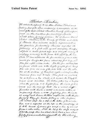
The schedule referred to in the Letters Patent and making part of the same, containing a description in the words of the said Robert Rankin himself of his improvement in the Machine for Moulding Bricks.
To all whom it may concern, Be it known that I, Robert Rankin, of Frankfort, in the County of Wollo and State of Maine, have invented certain improvements in the Machine for Moulding Bricks and that the following is a full and exact description thereof.
A frame is made of such size and strength as may be necessary, according to the frame to be applied, in one which I have constructed the foundation or ground sill consist of a horizontal frame about six feet long, and three feet eight inches wide. Into this four vertical posts are framed which rise to the height of eight feet: two of these rise from one end of the side sill and the other two at the distance of three feet eight inches from them measured from out to out. These posts are enclosed so as to form a box which is to contain the Clay to be mixed and moulded. The bottom of this box is twofold above the ground, & its height four; the inside of it is round and the mixing wheel has a vertical shaft furnished with knives or cutters to revolve within it comprising knives or rods, projecting from the inside six away well known to those acquainted with the preparing of Clay for bricks, pottery or other purposes.
The vertical shaft has a step in the bottom of the circular box, and is supported at the top in the usual way, it is to be turned by means of a sweep or lever by animal power or other wise. Near the top of this shaft and just below the sweep there is a wheel which serves as a wheel freely fixed on and turning with it. This wheel is
Page 3.
United States Patent
Patent No.: X8562
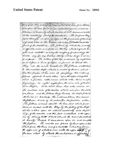
four feet two inches in diameter and one foot thick, and upon it are formed an eccentric groove, inclined planes, 40 ones, by which motion is to be communicated to the moulding part of the machine. The prepared clay passes through an opening, left in the front side of the moulding well close to the bottom, into a box, which I call the front of the machine. The follower by which the moulding is effected rises and falls in the box, which is of such length and width as may be necessary for moulding the bricks, say for six bricks thirty inches long and one foot wide. The bottom of this box is divided by cross bars so as to form a kind of hopper or funnel to direct the clay into the mould beneath it. The follower is attached to the vertical shaft which is moved by the cam wheel. For this purpose it has near its periphery two inclined planes opposite to each other; upon the upper side of this wheel a friction roller runs, which roller turns on a pin projecting at right angles from the inner side of the follower shaft. As the wheel turns this roller moves at the vertical side of the cam, which rises from the inclined planes and the follower being lowered, the shaft falls to the bricks in moulding, the inclined planes then cause the follower to rise by its action on the friction roller. The follower is made double: the lower part which first comes in contact with the clay by the falling of the shaft strikes a block upon it which materially aids the falling of the moulds and this part is attached to the upper one by sliding bolts which admit the second part which is heavily loaded to come down upon it and complete the pressure. The moulds are placed by hand upon a box which forms the lower end of a vertical vibrating frame, the upper end of which is connected with the upper surface of the cam wheel by which the vibration is effected.
Page 4.
United States Patent
Patent No.: X8562
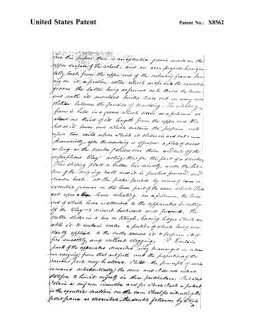
For this purpose there is an eccentric groove made on the upper surface of the wheel, and an arm projects horizontally back from the upper end of the vibrating frame, having on it a friction roller which drops into the eccentric groove the latter being so formed as to throw the lower end with its moulded bricks twice out in every revolution between the periods of moulding. The vibrating frame is held in a groove which serves as a fulcrum at about one third of its length from the upper end. The bed at its lower end which sustains the pressure rests upon two rails upon which it slides in and out.
Immediately after the moulding is effected a plate of metal as long as the moulds slides over them and cuts off the superfluous clay acting thus for the part of a striker. This sliding plate or cutter lies directly under the bottom of the moulding well and it is pushed forward, and drawn back, at the proper periods by means of cams or eccentric grooves on the lower part of the cam wheel. These act upon a lever vibrating on a fulcrum, the lower end of which lever is attached to the apparatus for cutting off the clay and draws it backward only forward, the cutter slides in a box or trough, having ledges which enable it to contain water a portion of which being constantly applied to the cutter causes it to perform its office smoothly, and without clogging.
The particular parts of the apparatus described may be arranged in a manner varying from that set forth, and the proportions of the various parts may be altered, whilst the principle of action remains substantially the same and I do not intend therefore to limit myself in these particulars. But what I claim as my own invention, and for which I ask a patent is the eccentric motion on the cam wheel for vibrating the front frame as described, the double follower by which
Page 5.
United States Patent
Patent No.: X8562
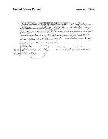
a block is first struck upon the metal and heavy pressure afterwards made. The sliding cutter with its apparatus (operating) in the manner described, and the general arrangement & combination of the respective parts, by which this machine differs in its character from all others previously used for the same purpose.
Witnesses:
H.B. Fleet W. Smith
Robert Benskin
Henry John Page
Published accounts: journal notice
Notice in the monthly list of patents
Journal of the Franklin Institute, new ser., vol. 15 (1835), p. 144 · View the page
628. Moulding bricks. Robert Rankin, Frankfort, Maine,
Published accounts: journal notice
Notice in the monthly list of patents
Journal of the Franklin Institute, new ser., vol. 16 (1835), p. 35 · View the page
58. For a Machine for Moulding Bricks; Robert Ranken, Frankfort, Waldo county, Maine, December 23.
About this record
- Patentee
- the Journal of the Franklin Institute, Journal
- Date
- USPTO records, Jim Shaw's X-patent list, Burke's List of Patents (1847)
- Invention
- the Name and Date index of patents
- Listed in
- the Name and Date index of patents, USPTO records, Jim Shaw's X-patent list, the Journal of the Franklin Institute, Burke's List of Patents (1847)
- The sources give different dates; the date shown is the one most of them agree on.
- The patentee's full name comes from the Franklin Institute's journal.
- The Franklin Institute's journal confirms the date shown.
- Burke's 1847 Patent Office list gives the same patent.