

Drawings and documents
USPTO scan
The patent as scanned by the USPTO
-
 Page 1
-
 Page 2
-
 Page 3
-
 Page 4
-
 Page 5
-
 Page 6
-
 Page 7
-
 Page 8
-
 Page 9
-
 Page 10


U.S. Patent and Trademark Office · Google Patents
Show the transcription Hide (2,788 words)
Machine transcription (LightOnOCR) of the pages as scanned by the USPTO, most of them the handwritten copies made when the records were restored after the 1836 fire. Not checked; it can misread handwriting, so compare it with the scan.
Page 2.
United States Patent
Patent No.: X8587
Ethan Baldwin
Letters Patent
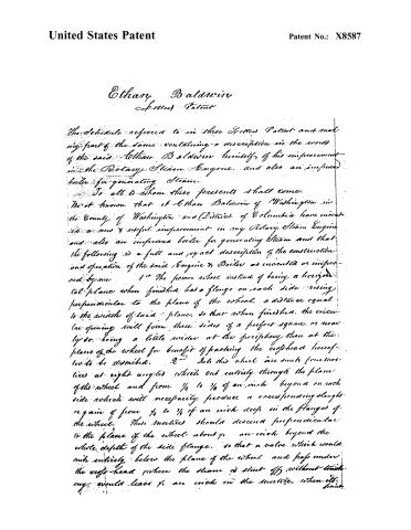
The Schedule referred to in these Letters Patent and making part of the same containing a description in the words of the said Ethan Baldwin himself, of his improvement in the Rotary Steam Engine, and also an improved boiler for generating Steam.
To all to whom these presents shall come.
Be it known that I, Ethan Baldwin of Washington in the County of Washington and District of Columbia have invented a new & useful improvement in my Rotary Steam Engine and also an improved boiler for generating Steam and that the following is a full and exact description of the construction and operation of the said Engine & Boiler as invented or improved by me.
1st The power wheel instead of being a horizontal plane when finished has a flange on each side rising perpendicular to the plane of the wheel, a distance equal to the width of said plane, so that when finished, the circular opening will form three sides of a perfect square, or nearly so, being a little wider at the periphery than at the plane of the wheel for benefit of packing the crosshead hereof to be described.
2nd Into this wheel are sunk four mortices at right angles which cut entirely through the plane of the wheel and from ¼ to ½ of an inch beyond on each side which will necessarily produce a corresponding slant or gain of from ¼ to ½ of an inch deep in the flanges of the wheel. These mortices should descend perpendicular to the plane of the wheel about ½ an inch beyond the whole depth of the side flange, so that a valve which would sink entirely below the plane of the wheel and pass under the cross-head where the steam is shut off without touching, would leave ½ an inch in the mortice, when it
Page 3.
United States Patent
Patent No.: X8587
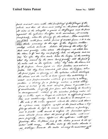
point was out even with the periphery of the flange of the wheel, and thus, its lower end resting on the plane of the wheel, its sides in the slugs or gaps in the flanges and its point against the cylinder hereafter to be described, it would completely close the opening of the wheel. These receptacles are filled with four solid pieces of metal from 1 to 3 inches thick according to the size of the Engine called valves which descend below the plane of the wheel by their own gravity, when above the horizon, at which time the steam is off and they are perfectly loose in the gaps and move free but after they have sunk below the horizon in the revolving wheel they descend by the same law of gravity till the point of the valve rests on the cylinder where they take the steam, and by its pressure, become fixed in that position and act as a piston till they have ascended just above the horizon, where the point paves an opening in the cylinder which discharges the steam and the valve is loose again—thus substituting a direct and perpendicular instead of a circular & rotary motion, a sliding for a folding valve, a solid alloy piece of metal of the most simple form & greatest ease of construction, perfectly free from all liability to breaking or derangement, instead of the circular folding valve moving on either axis or hinge so intricate & difficult of construction and continually liable to break or be deranged.
The side of the valve against which the steam acts should be a plane even surface except at the point where a large flange should be left to receive the vulcan or packing, and a plate with screws to confine it, provided experience should prove that the point of the valve will and more perfectly steam tight in the cylinder with soft packing than the plane end of the valve ground to the cylinder with energy. The other side of the valve should be as dishing towards the centre as may be consistent with the
Page 4.
United States Patent
Patent No.: X8587
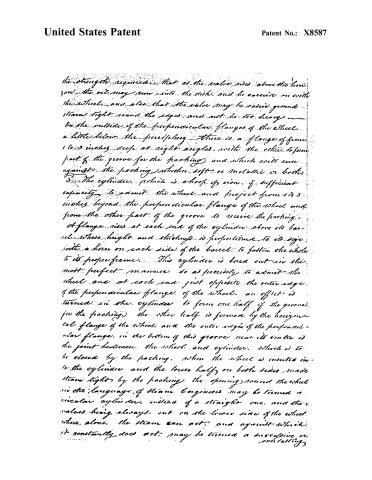
the strength required. That as the valve rises above the line you the oil may run into the dish and be carried on with the wheel, and also that the valve may be easily ground steam tight round the edges and not be too heavy. On the outside of the perpendicular flanges of the wheel, a little below the periphery there is a flange of from 1 to 3 inches deep at right angles with the other, to form part of the groove for the packing, and which will run against the packing whether soft or metallic or both. 3. The cylinder, which is a loop of iron, of sufficient capacity to admit the wheel and project from 1 to 3 inches beyond the perpendicular flange of the wheel and from the other part of the groove to receive the packing. A flange rises at each end of the cylinder above its barrel whose height and thickness is proportioned to its size with a horn on each side of the barrel to fasten the whole to its proper frame. This cylinder is bored out in the most perfect manner so as precisely to admit the wheel and at each end just opposite the outer edge of the perpendicular flange of the wheel, an offset is turned in the cylinder to form one half of the groove for the packing; the other half is formed by the horizontal flange of the wheel and the outer edge of the perpendicular flange. In the bottom of this groove near its centre is the joint between the wheel and cylinder, which is to be closed by the packing. When the wheel is inserted into the cylinder and the lower half on both sides made steam tight by the packing, the opening round the wheel in the language of steam engineers may be termed a circular cylinder, instead of a straight one, and the valves being always, cut on the lower side of the wheel where alone, the steam can act, and against which it constantly does act, may be termed a double or self-acting.
Page 5.
United States Patent
Patent No.: X8587
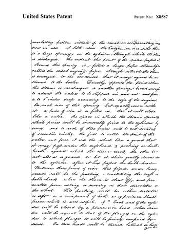
everlasting piston, instead of the usual or reciprocating one now in use. A little above the horizon on one side there is a large opening in the cylinder, through which the steam is discharged. The instant the point of the valve passes it, from this opening is fitted a large pipe, steam-tight, called the condensing pipe, through which the steam is conveyed to the condenser, that it may again be returned to the boiler. Directly opposite the point where the steam is discharged is another opening broad enough to admit the valves to be slipped in and out, and from 2 to 6 inches deep according to the size of the engine. On each side of this opening, but exactly even with it, a piece of iron is so fitted in, that it will close like a valve. The space in which the steam operates, which pieces will be immovably fixed to the cylinder by screws, and to each of these pieces will be cast sections of eccentric circles, the first to catch the point of the valve, and force it into the wheel, like a guard that it may pass under the cylinder & packing or bulk-head, against which the steam reacts; the other to act also as a guard to let it slide gently down into the cylinder, after it has passed the bulk-head. Between these pieces of iron thus fixed, under heavy screws, will be the packing, constituting the orifices or bulk-head, where the steam is shut off, and prevented from acting or moving in that direction on the wheel. This packing, will be either metallic or soft, or a compound of both, as experience shall prove which is most useful. At each end of the cylinder will be closed by a plane-iron head, whose diameter will be equal to that of the flanges on the cylinder to which flanges it will be firmly confined by screws. On these heads will be turned lateral or horizontal
Page 6.
United States Patent
Patent No.: X8587
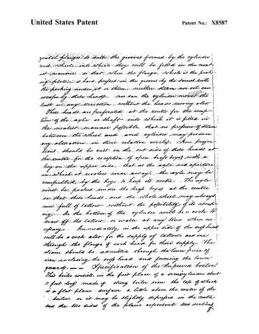
horizontal flanges to enter the grooves formed by the cylinder and wheel into which they will be fitted in the nearest manner, so that when the flange, which is the packing plate, is hard pressed in the grooves by the screws, with the packing under it or them, neither steam nor oil can escape by these heads. nor can the cylinder move the least in any direction, without the heads moving also.
These heads are perforated at the centre for the reception of the axle or shaft into which it is fitted in the nearest manner possible, that no pressure of steam between the wheel and cylinder may produce any alteration in their relative circles. Iron projections should be cast on the out side of these heads at the centre for the reception of open brass boxes with a key on the upper side, that as the axle and aperture in which it revolves wear away, the axle may be compelled, by the keys, to keep its centre. The axle must be packed under the brass boxes at the centre so that these heads and the whole wheel may always run full of tallow without the possibility of its escaping. In the bottom of the cylinder will be a cock to draw off the tallow, or water at any time when necessary. Immediately in the upper side of the egg-head will be a cock also for the supply of tallow and one through the flange of each head for their supply. The steam should be admitted through the lower piece of iron enclosing the egg-head and forming the lower guard.
Specification of the Improved Boiler.
This boiler consists in the first place of a semi-cylinder about 5 feet long made of strong boiler iron the top of which is a flat plane surface a little above the centre of the boiler, or it may be slightly depressed in the centre and the two sides of the plane represent two sections of
Page 7.
United States Patent
Patent No.: X8587
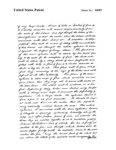
of very large circles. A row of tubes or heaters of from 4 to 6 inches diameter will descend perpendicularly from the centre of this plane and pass through the bottom of the semi-cylinder, so that the water above the plane will communicate with that below it. In addition to these supports there will be a row of strong bolts on each side of these heaters up through the outside cylinder, to secure it against the pressure of heavy steam. The front end of this semi-cylinder will be closed by two doors opening to the centre for the admission of fuel. The back end will be closed by a strong plate of iron perforated and filled with tubes or flues of from 4 to 6 inches diameter as thick as they can be set. These flues will be from 15 to 30 feet long according to the size of the boiler and will pass out at its other extremity. The plane of the semi-cylinder & proper range of flues should constitute one uniform plane, that they may all be covered with water at the same time. The whole must be enclosed in a perfect cylinder of strong boiler iron looped every foot with a strong iron hoop to prevent the possibility of explosion. In a large boiler the cylinder should be from 4 feet to 4½ feet diameter. It should be larger at each end than in the centre, that the deposits may naturally incline toward the ends. This outside cylinder is connected with the semi-cylinder by means of sloughs or openings extending laterally along the sides, and after proper pieces of iron are inserted between, they are riveted together so as to constitute grating between the hollow bars of which, the air is freely admitted to the fire, and through which hollow bars the water passes freely with the deposits, down to the centre under the fire, being the lowest part of the whole boiler, where the whole of the deposits will necessarily be rejected.
Page 8.
United States Patent
Patent No.: X8587
collected. Directly in the bottom, under the perpendicular tubes, there will be no grating for a space of from 8 to 12 inches, the outer and semi cylinder at this point being unconnected and distant from each other from 2 to 5 inches leaving no obstruction to the extraction of the deposited or sediment at the front end through the bonnet or door, left for that purpose. There will be a bonnet in the back end for the same purpose. When the boiler is set, the brickwork will not be permitted to approach nearer the outside cylinder than 6 inches till it rises to a level with the water line in the boiler, and then a range of brick will project tight against the boiler at the back end and directly over the flues & along the sides, till within two feet of the front, then it will stop and let the fire rise, after passing out of the flues & traversing the sides of the boiler, and run back over the top of the boiler, to the back end again before it takes the smoke-stack. A sheet iron cover, stiff, covered with some non-conductor of caloric, will be set over the boiler resting on the brickwork at the sides and at a sufficient distance from the boiler to allow free passage for the fire or heated air to pass through to the smoke-stack. Thus the fire will be compelled to traverse the whole length of the boiler three times before it is permitted to escape. The advantages of this improved boiler over any now known or in use are believed to be the following: 1st the fire is entirely within the boiler surrounded by water, and all extra grating dispensed with. 2nd There is less danger of fire to the boat or machinery. 3rd as every part of the boiler is exposed to the fire on one side & to the water or steam on the other, except about 18 inches wide along the bottom of the outside cylinder, on which the sediment
Page 9.
United States Patent
Patent No.: X8587
sediment collects, there is the greatest possible exposure to the fire which can be made in any boiler. 4th As the flues are set as thick as workmanship can set them, there will be no large column or body of water in the boiler in any place, and for its capacity, this boiler will contain and carry the least possible quantity of water, and as steam is generated with a rapidity proportioned to the thickness of the plates of water exposed to the heated surfaces, so the same number of superficial feet of boiler iron will produce a greater quantity of steam in this form than any other now known. 5th As the fire is made to traverse the boiler three times previous to its escape and is divided into small columns, the whole of whose sides are constantly exposed to the boiler, it is confidently believed that it will impart in its progress all its excess of caloric above the temperature of the steam, to the boiler, so that no heat created by the fuel will pass off unimproved, and it is as confidently believed that the same quantity of fuel in this form of boiler will produce from 50 to 100 per cent of steam more than any one now known. 6th As no sediment will be deposited on any part of the boiler exposed to the direct action of the fire, the danger of injury to the boiler and consequent explosion from that source will be avoided. 7th The boiler will be much smaller and lighter in proportion to its power than any one now in use, and as all its parts, except the plane over the semi cylinder consists of cylinders or arches, all of which will be small except the outside cylinder, this being made of thick iron and well hooped, it may be safely affirmed that a boiler of this construction, and the same weight of another will be able to produce sustain and exert double the effective power.
Page 10.
United States Patent
Patent No.: X8587
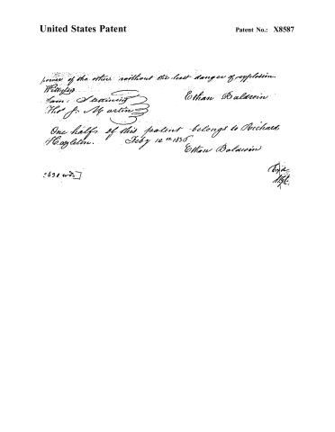
power of the other, without the least danger of explosion.
Witness:
Ethan Baldwin
One half of this patent belongs to Richard H. Cagleton.
July 12th 1856
Ethan Baldwin
2630 wts
Published accounts: journal notice
Notice in the monthly list of patents, with remarks
Journal of the Franklin Institute, new ser., vol. 16 (1835), p. 89 · View the page
21. For an improvement in the Rotary Steam Engine, and an improved boiler for generating steam; Ethan Baldwin, city of Washington, District of Columbia, January 13.
Remarks. We gave a brief notice of the rotary engine patented by the same gentleman, on the 28th of January, 1833, upon which this is said to be an improvement, but to us it appears that the present engine is as distinct from the former in its particular arrangements, as many of the rotary engines which have been patented, are from each other. It will be seen by turning to vol. xii., p. 31, that, in the former engine, folding valves were used to close the annular cavity, or chamber. In the present engine, the valves, four in number, are to slide into the body of a solid revolving cylinder, much in the manner of those in Bramah & Dickinson's, patented in England in the year 1790; the valves in the present instance, however, are each distinct in its operation, not being united with that which is opposite to it. These valves are to slide in and out by their own gravity, or rather, as we should suppose, they are to slide out by the centrifugal force under VOL. XVI. No. 2.-AUGUST, 1835. 12 which they will operate, in their rapid motion, and to slide in by the action of the curved part, called by the patentee a bulk head. Stuffing is spoken of as intended to be applied to the valves, but it is mentioned rather as a thing of experiment than of certainty. We are in this, as in the former patent, left altogether to conjecture respecting what it was intended to patent, no part of the apparatus described being claimed, nor any distinction made between what is old, and what is supposed to be new. On this point, and some others, we refer to the concluding remarks made on the former patent, as indicating the opinion entertained by us of the present machine. We shall be glad to find ourselves in error, as we hail all real improvements, and, in the present instance, take a friendly interest in the success of the patentee. The boiler described is, in its general construction, like that of Stevenson, as used in locomotive engines, but with certain specified variations. The fireplace is to be in the form of a semi-cylinder, and entirely within the horizontal cylinder constituting the boiler, its flat side being uppermost, and below the water line. Vertical tubes are to pass through the top and bottom of this fireplace, to admit water through them; and horizontal tubes, from four to six inches in diameter, are to be placed as in Stevenson's boiler. The top of the cylinder is to have flues of sheet iron extending along it, conducting the heated air passing through the tubes, back again to the front, and then again to the back of the boiler, before it escapes at the chimney; these, of course, heat the steam only. Many advantages are enumerated, which are expected to result from a boiler so constructed, that we are very apprehensive will never be realized; we think it liable to many objections, and among them would name the vertical tubes in the fireplace, and the large size of the horizontal tubes. There are some points noted by the patentee, for example, hooping the boiler to prevent explosion, which we have not room to introduce. As regards this boiler, as well as his rotary engine, the patentee has neglected to discriminate between the new and the old, having described the affair as though the whole was original, which is very far, indeed, from being the case.
About this record
- Patentee
- DATAMP
- Date
- the Name and Date index of patents, DATAMP, USPTO records
- Invention
- DATAMP
- Listed in
- the Name and Date index of patents, DATAMP, USPTO records, Jim Shaw's X-patent list, the Journal of the Franklin Institute, Burke's List of Patents (1847)
- Burke's 1847 Patent Office list gives the same patent.