

Drawings and documents
National Archives restored drawings: drawing
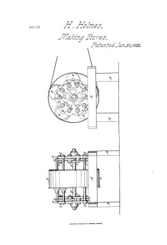
H. Holmes' Patent Drawing for a Machine for Sawing Staves

National Archives, Restored Patent Drawings (Record Group 241) · Full-size scan at the National Archives · Catalog record
Show the text on the drawing Hide (103 words)
Words on the drawing as machine-read by the National Archives; not checked. Useful mainly for searching.
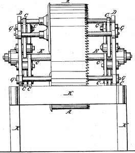
143. WOOD SAWING. / 143, moon WING. / SAWING MACHINE / Tubular Sawing Machines. Tubular Saw, / taves / H HOLME S / #2- / Jumbor / Saurni Staves / CLASSIFICATION / 8611-X / DIVISION. / Patented 1835 / A Cylendricol Saw / B. First set of freehon Rollers / c Second De D / D. Rims / E. Crojs-bar / F. S Square Holes to adjust the axles oz Journats of 2 seroj Rollers / G Adjusting SCTEWS / H. Guards / K. Frame / On / Oa / Oa / OF / Band / G Strickland Det / Patent offin 3 Nov 1838 / Madi under the direction of the Communication / of Patients in conformity with act3 March 1837 / of Patents
USPTO scan
The patent as scanned by the USPTO
-
 Page 1
-
 Page 2
-
 Page 3
-
 Page 4


U.S. Patent and Trademark Office · Google Patents
Show the transcription Hide (1,063 words)
Machine transcription (LightOnOCR) of the pages as scanned by the USPTO, most of them the handwritten copies made when the records were restored after the 1836 fire. Not checked; it can misread handwriting, so compare it with the scan.
Page 1.
8611X
H. Holmes,
Making Stares.
Patented Jan. 21, 1895.

A.M. PHOTO-LITHO. CO. N. Y. (OSBORNE'S PROCESS)
Page 2.
Jan. 21, 1835
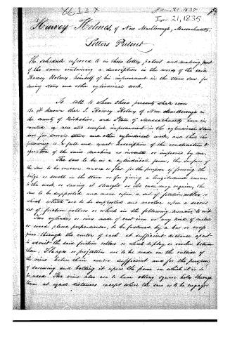
Harvey Holmes, of New Marlborough, Massachusetts,
Letters Patent
The schedule referred to in these letters patent and making part of the same containing a description in the words of the said Harvey Holmes, himself of his improvement in the stone saw for sawing staves and other cylindrical work.
To all to whom these presents shall come
Be it known that I, Harvey Holmes of New Marlborough in the county of Berkshire, and State of Massachusetts have invented a new and useful improvement in the cylindrical stone saw for sawing staves and other cylindrical work, and that the following is a full and exact description of the construction & operation of the said machine as invented or improved by me.
The saw to be in a cylindrical form, the surface of the saw to be concave convex or flat for the purpose of forming the hige or swell in the stave or for giving a longitudinal curve to the work, or sawing it straight as the case may require, the saw to be supported and move upon a set of friction rollers or wheels which are to be supported and revolve upon a second set of friction rollers or wheels in the following manner, to wit:
Two cylinders or rims made of cast iron or any kind of metal or wood placed perpendicular, to be fastened by a bar or cross piece through the centre of each at sufficient distance apart to admit the said friction rollers or wheels to play or revolve between them. Flanges or projections are to be made on the outside of the rims below their centre sufficient and for the purpose of screwing and bolting it upon the frame on which it is to be used. The rims also are to have oblong square holes through them at equal distances except where the saw is to be engaged.
Page 3.
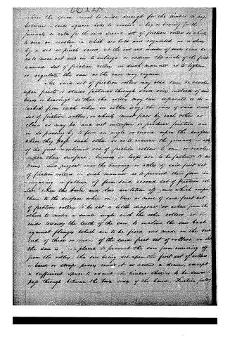
where the space cannot be wide enough for the timber to pass between—such square holes to receive a box or bearing for the journals or axles for the said second set of friction rollers or wheels to run or revolve in which are held and regulated as a slide by a set or pinch screws, at the end and inside of said rims to act to move out and in to enlarge or reduce the circle of the first named set of friction rollers in such manner as to tighten or regulate the saw as the case may require.
The said set of friction rollers may also run or revolve upon pivots or studs fastened through said rims instead of said boxes or bearings so that the rollers may run separate or detached from each other in either way; the rims of said second set of friction rollers, or wheels must pass by each other as close as may be and not interfere or produce friction and in so passing by to form an angle or curve upon the surface where they pass each other so as to receive the journals or axles of the first mentioned set of friction rollers to run or revolve upon their surface; screws or loops are to be fastened to said rims and project over the bearings or axles of said first set of friction rollers in such manner as to prevent them from disengaging or falling off from said second set of friction rollers when the bands and saw are taken off and which confine them to the surface when on. One or more of said first set of friction rollers to be set a little diagonal or askew from the others to make a small angle with the other rollers, at the ends toward the teeth of the saw, to incline the saw back against flanges which are to be fixed and made on the back end of three or more of the said first set of rollers on which the saw is placed to prevent the saw from running off from the rollers, the saw being set upon the first set of rollers a band or strap passing round it as over a drum, except a sufficient space to admit the timber that is to be sawed to pass through between the two rims of the band. Friction fully
Page 4.
8611X
are placed one above, and one below the carriage that carries the timber to be sawed to keep the band close to the saw, - The top or upper pulley to be held by an arm attached to one of the rings, the other to the frame below, The timber to be sawed to be carried between the side of the band where they have the saw, on a carriage. The band passing around the saw, also passes over the drum separate from the machine and propelled by any revolving power, all of the above mentioned wheels or rollers to be made of any kind of metal or wood. It will require about nine of the first named set of friction rollers or wheels and about twenty of the second set for a saw two feet in diameter which is the proper size for a barrel and for other uses in proportion.
What I claim as my invention in the above described machine is an improvement in the application of the second set of friction rollers or wheels for the journal or axles of the first named set of friction rollers or wheels to run or revolve upon their surface to prevent friction and thereby to accelerate the speed or motion of the saw so as to enable more work or business to be performed in the same time than of any other machine.
For further illustration of the same I refer to the model and drawing of same deposited in the Patent Office.
In witness whereof I have this fifteenth day of September in the year of our Lord one thousand eight hundred and thirty-four, subscribed my name.
Witness
Harvey Holmes
M. J. Wilson
E. C. Farland
(1023 words)
Published accounts: journal notice
Notice in the monthly list of patents, with remarks
Journal of the Franklin Institute, new ser., vol. 16 (1835), p. 98 · View the page
This is to be a cast-iron mill, and it is made so much like some others, that it would be no easy task to find the part in which its novelty lies. We are told that "the said conic grinder is suitable to grind all manner of grain, of which we claim to be the inventors, so much of it, however, as relates in a particular manner to the cone and runner, and their operation together, and no more." The patentees can, no doubt, see something peculiar in their conical nut and shell, but they not having pointed directly to it, we are unable to find it out. 43. For a Saw for Sawing Staves, and other cylindrical work; Harvey Holmes, New Marlborough, Berkshire county, Massachusetts, January 21.
Remarks. The sawing is to be effected by means of a hoop saw, sustained upon friction rollers, in a way which we have had occasion to describe more than once; but the present patentee thinks that he has improved the apparatus, by causing the gudgeons of the friction rollers which sustain the saw, to run upon other friction rollers. He claims "the application of the second set of friction rollers, or wheels, for the journals or axles of the first named set of friction rollers, or wheels, to run or revolve upon their surface, to prevent friction, and thereby to accelerate the speed or motion of the saw, so as to enable more work or business to be performed in the same time, than by any other machine." We know not in whom the right to the hoop saw vests, but if not in the present patentee, his so called improvement will not secure it to him. We are of opinion, however, that the additional friction rollers will involve more loss by their complexity, and the expense of their construction, than they will repay by diminishing friction. It will be found, in practice, that many of these wheels will stand still, and allow the gudgeons to revolve upon their surfaces, more especially when saw dust, or other foreign matter, adheres to them. For some preceding remarks on a saw of this kind, see vol. xv., p. 93, and vol. xiii., p. 121.
DATAMP: illustration
Illustrations from DATAMP

DATAMP (Directory of American Tool and Machinery Patents), via the Internet Archive · Archived DATAMP page
About this record
- Patentee
- DATAMP
- Date
- the Name and Date index of patents, DATAMP, USPTO records
- Invention
- DATAMP
- Listed in
- the Name and Date index of patents, DATAMP, USPTO records, Jim Shaw's X-patent list, the Journal of the Franklin Institute, Burke's List of Patents (1847)
- Burke's 1847 Patent Office list gives the same patent.