

Drawings and documents
USPTO scan
The patent as scanned by the USPTO
-
 Page 1
-
 Page 2
-
 Page 3
-
 Page 4
-
 Page 5
-
 Page 6
-
 Page 7
-
 Page 8
-
 Page 9


U.S. Patent and Trademark Office · Google Patents
Show the transcription Hide (3,089 words)
Machine transcription (LightOnOCR) of the pages as scanned by the USPTO, most of them the handwritten copies made when the records were restored after the 1836 fire. Not checked; it can misread handwriting, so compare it with the scan.
Page 2.
United States Patent
Patent No.: X8625
Stephen Ustick
Patent for a Strawcutter
The Schedule referred to in these Letters Patent, and making part of the same, containing a description in the words of the said Stephen Ustick himself, of his improvement in his Strawcutter, for which he obtained from the United States Letters Patent bearing date October 3rd, 1834.
To all to whom these Presents shall come
Be it Known, that I, Stephen Ustick of Philadelphia, in the county of Philadelphia, and State of Pennsylvania, have invented a new and useful improvement on the Strawcutter, for which I obtained Letters Patent, from the United States, bearing date October 3rd, 1834, a Schedule of which is given below, and that the specification given succeeding said Schedule, is a full and exact description of the construction and operation of the said improvement as invented by me.
Schedule referred to above — To all to whom these Presents shall come, Be it Known, that I, Stephen Ustick of Philadelphia, in the county of Philadelphia, and State of Pennsylvania, have invented a new and useful improvement on the Strawcutter, for cutting straw, hay, & cornstalks, called Stephen Ustick’s Strawcutter, and that the following is a full and exact description of the construction and operation of the said machine as invented by me.
In the first place I have a frame constructed as follows — two posts, which I call the front trough posts, are framed into a base, one foot asunder; said basepiece extends beyond the right hand post, and has a post, which I call the first crank post, framed into it 6 inches from said post; the first crank post is framed at its top into one end of a rail, which is framed at its other end into the right hand trough post above specified. This rail serves as a foundation for a
Page 3.
United States Patent
Patent No.: X8625
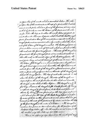
a guigeon box of the crank which is described below. The other guigeon box of the crank rests on the top of a post, which I call the second crank post, which is in front of the first one, and connected with it by 2 rails, one near the bottom of the posts, and the other as far below the top, as to allow the crank below specified, to work above it. There are 2 posts which I call the back trough posts, formed into a base of the same distance asunder as the front trough posts, and are connected above by a rail, on which the back end of the bottom of the trough is nailed. The back trough posts are framed below on one end of two rails which are framed at their other end into the front trough posts. The sides of the trough are framed into the front trough posts at one end, and nailed at their other end, on the inside edges of the back trough posts, the said posts being cut out the thickness of the sides to receive them. The bottom of the trough is in a horizontal position lengthwise. The right hand edge is one inch lower than the left hand one; it extends from the back of the trough to a fluted cast iron feed roller in front, whose guigeons turn in the sides of the trough, just behind the trough posts. This top of said roller extends 1 inch above the bottom of the trough. The sides of the trough are tapered from the said feed roller to their back end to make the trough wider behind than before. This trough is only 2 feet long. I extend the trough 2 ft. 6 inches further, by having a separate trough to fit at front, to its back and fastened thereto, by having of iron fastened on the top edges, at front which extend over the tops of the back trough posts and fit by means of holes in their front ends on iron pins, which are permanent in the ends of the posts, and by strips nailed on the back of the first trough, at the sides and bottom. The trough is made in two pieces, as described above, for the purpose of the back part being taken off when the machine is not in use, so that the machine may then take up but little room.
There is an opposing edge fastened on the mouth of the trough
Page 4.
United States Patent
Patent No.: X8625
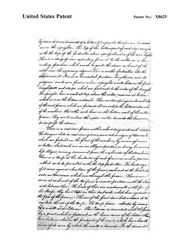
by means of screws, it consists of a bottom of 2 uprights to the frame — The screws are in the uprights — The top of the bottom part of said edge ranges with the top of the feedroller above specified and is of the same height. There is a strip of iron extending from it to the roller in a descending position which serves to guide the straw in front of the roller over the opposing edge. There is another feedroller like the above over it. It is in a horizontal position, lengthwise, and its guidecons works on a frame whose uprights works between the front troughposts and strips, which are fastened to the sides of the trough. The uprights have a rail at top above the roller, and one at bottom which is near the bottom side rails. There are two springs, one to each side of the said frame, which are fastened at one end, to the bottom side rails of the machine; their other ends bear on the bottom rail of the roller frame. They are to incline the upper roller towards the lower one, to compress the straw.
There is a cast iron frame with a short tongue at each corner. The tongues slide in cast iron grooves inserted in edges of two rails, which are fastened on the front of the machine, by means of screws or bolts. Said rails are in an oblique position, and may be more or less oblique, running downward from the right side of the machine. There is a knife at the backside of said frame, in such a position with it as to be parallel with the top feedroller. The back edge of it comes against shoulders of the frame, each end at the level side rests on two screws which run through the frame. There is one screw at each end of the knife, in a counter position with the above and between them. The heads of these are countersunk in the face of the knife; they have taps on their tail ends, which bear against the face of the frame. The use of the first described screws is to regulate the set of the knife. The knife frame vibrates by means of a crank and Petman. The Petman is connected with the frame by a pivot which is fastened in the lower corner of the latter. There is a balance wheel on the front end of the crank, which has a handle on one of its arms by which the crank is turned. In the downward
Page 5.
United States Patent
Patent No.: X8625
motion of the knife frame, the knife cuts the straw, when it has nearly returned, the straw is fed by means of a slope knob of the lower end of the frame working against the front end of the horizontal shaft, which works on boxes that are screwed to the trough posts of that side of the machine, there being a catch hung on the inside of said shaft, which operates on a ratchet wheel of the bottom roller and one hung to an upright of said shaft operates on a ratchet wheel of the top roller. The upper catch is above its ratchet wheel, the lower one is below its ratchet wheel, it is kept up against the ratchet wheel by its tail end being heavier than its bill part. The top roller is kept from turning backwards, by means of two palls hung on the upright of the roller frame, operating on the ratchet wheel. The bottom roller is kept from turning backwards, by two palls hung on the guiding strip of the roller frame, at that side of the machine. The upright of the roller frame has a slot in it, which works over the guide pin of the bottom roller on which the ratchet wheel is. As the knife goes down, the catch shaft above described slips forwards by means of a half circle spring, whose tail bears against the tail box of the catch shaft. The feed of the roller is regulated by a flat head screw in the back end of the catch shaft, which slides in the hole of the plate fastened on the trough posts. The head of said screw coming against the plate prevents the catch shaft above described being pushed too far forward by the spring above it.
There is a board, with the grain of the wood running perp. to the, fastened to the upper rail of the roller frame above described, in front of the upper roller, extending to within 1/2 inch in height of the bottom of the roller. Its face is nearly as far in front as the opposing edge. The use of it is to prevent the straw from being raised by the knife in its upward motion.
By the position of the knife and the opposing edge with the rollers, and the direction of the knife frame as described above I get a much greater draw of the knife on the straw, than can
Page 6.
United States Patent
Patent No.: X8625
therein be obtained with a crank of equal length, which makes it cut much easier.
What I claim as my invention, is the arrangement of the bottom of the trough, the opposing edge, the feed rollers, the position of the knife, and the direction of the knife frame collectively and the general construction of the Machine as described above.
I hereby certify that the above is my invention, and I have hereunto affixed my hand this nineteenth day of September in the year of our Lord One thousand, eight hundred and thirty-four.
Witnesses
John Binns
Allen Ward
Stephen Hock
The improvement for which I now solicit Letters Patent consists in apparatus for feeding and carrying the straw in lieu of that described in the above Schedule and which is of the following construction.
There is a groove in each side of the front trough within one inch of the bottom edge, the top edge of which ranges with the opposing edge. The bottom of the trough consists of three pieces of board, the grain of which runs crosswise, fit in said grooves. The first of said pieces is 6½ inches wide, the second, which I call the lower feeder, 8 wide, and the third commences within 9½ inches of the first and extends to the back of the trough. The first and third are stationary, but the second one, or lower feeder is slid backward and forward in the grooves described above, as described below.
There is a piece of sheet iron screwed on the face of said feeder, at the front edge, which extends over the back edge of the first piece of bottom, and there is a similar piece attached in the same manner, to the third piece, which extends over the back edge of the feeder. They are to break the pieces in front and back of the feeder, to prevent the straw from catching thereon as the feeder vibrates.
There is a perpendicular frame, whose base is screwed on blocks
Page 7.
United States Patent
Patent No.: X8625
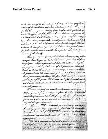
on the lower side of the above specified feeder, and whose uprights are outside of the trough sides, and which extend one foot above them, in each of which there is a groove extending from 1/2 of an inch of the side upwards. The upper rail of the frame is grooved behind said grooves. There is a board which I call the upper feeder, one foot wide, whose ends from its upper edge slide in said grooves. The lower part of the ends is cut out, to allow the feeder to descend in the trough. There is a box on the face of said feeder, which holds sand, or gravel, to compress the straw between it and the lower feeder. The feeder forms one side of the box.
There is a square frame, which I call the camprefor, whose uprights have tongues on them, which slide in grooves of the front trough posts. Said tongues extend below the bottom rail of the camprefor, and through the ends of the front piece of trough bottom, so that as the camprefor is elevated, as is described below, the grooves below the lower rail of it are still filled, to prevent straw from working in them. The face of the camprefor is flush with the face of the posts. The bottom rail of it, 4 inches deep and 3 inches thick, it extends at the ends over the uprights between the posts.
There is a strip of cast iron 12 inches wide, with edges on its face formed by square edges on front and back sides. Backward therefrom inserted in the face of the lower feeder at its front and a similar one, one inch wide, screwed on the lower edge of the upper feeder.
There is a cast iron 12 inches wide with edges on its face formed by square edges on front and back sides, to be removable from, inserted on the face of the lower feeder at its front and a similar one, one inch wide, screwed on the lower edge of the upper feeder.
There is a cast iron wheel with a groove on each side near its periphery, which fits eccentrically on the square of the tail end of the crank specified in the above schedule, which works a lever.
Page 8.
United States Patent
Patent No.: X8625
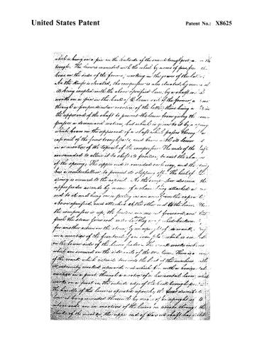
which is hung on a pin in the backside of the second troughpost, a on the trough. The lever is connected with the wheel by means of pins, from the holes on the sides of the former, working in the grooves of the latter. As the knife is elevated, the compressor is also elevated, by means of its being coupled with the above specified lever, by a shaft which works on a pin in the back of the lower rail of the former, a one through a perpendicular mortise of the latter; there being a pin in the upper end of the shaft to prevent the lever from giving the compressor a downward motion, but which is given to it by a spring which bears on the upper end of a shaft which passes through a cap rail of the front troughposts, and bears with its lower end in a mortise of the top rail of the compressor. The ends of the shaft are rounded to allow it to shift its position, to suit the changes of the springs. The upper end is rounded each way, and the spring has a countershallow to prevent its slipping off. The heel of the spring is screwed to the extrail. As the compressor descends, the upper feeder ascends by means of a chain being attached at one end to it, and hung on a pulley on an arm from the cap rail, above specified, and attached at the other end to the lever. When the compressor is up, the feeders are moved forward, and thus push the straw forward, and when they are pushed backward, for another action on the straw, by an upright of a crank, in a mortise of the front end of an iron plate which is screwed on the lower side of the lower feeder. The crank works in holes which are screwed on the side rails of the lower lever. There is a arm of the crank which extends towards the front of the machine, its extremity crooked upwards, and which fits with a horizontal mortise in a post, through a mortise of a horizontal lever, which works on a pivot in the outside edge of the back troughpost. The handle of this lever is operated upon by the hand described, the lever being connected therewith by means of an upright at its whose ends are in mortises of the levers in pins through the cheeks of the mortises, the upper end of the said shaft has a slot
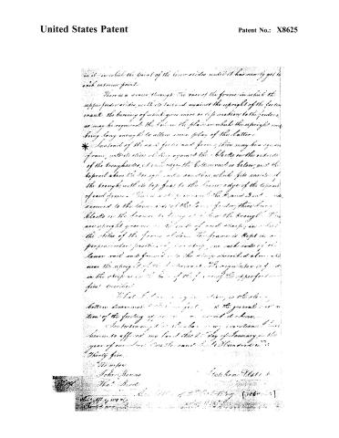
Page 9.
United States Patent
Patent No.: X8625
in it in which the pivot of the lever slides until it has nearly got to each extreme point.
There is a socket through the base of the frame in which the upper feeder slides, with its tail end against the upright of the feeder crank, the turning of which gives more or less motion to the feeders, as may be required. The hole in the plate in which the upright was being long enough to allow some play of the latter.
*In stead of the said feeder and frame, there may be a square frame, with its sides sliding against the blocks on the outside of the troughs, at one edge of the bottom rail is below, and the top rail above the trough, and a said one, which fits inside of the trough, with its top fast to the lower edge of the top rail of said frame. There is a strip across both the 2nd and 3rd rails, secured to the lower side of the lower feeder, there being blocks on the former to bring it below the trough. There are upright grooves in the ends of said strips, in which the sides of the frame slide. The frame is kept in a perpendicular position by two strips, one each side of the lower rail and formed into the strips described above, and near the upright of the feeder crank. The regulator is fixed in the strips as in the base of the frame of the upper feeders described.
What I claim as my invention is the said bottom, denominated the lower feeder, and the general construction of the feeding apparatus as described above.
In testimony that I have my invention I have hereunto affixed my hand this 21st day of January, in the year of our Lord One thousand eight hundred and thirty five.
Witnesses
John Thomas
Thos. Burd
Stephen Ustin
Published accounts: journal notice
Notice in the monthly list of patents, with remarks
Journal of the Franklin Institute, new ser., vol. 16 (1835), p. 157 · View the page
1. For an improvement in the Machine for Cutting Straw; patented October 3, 1834; Stephen Ustick, city of Philadelphia, February 5.
Remarks. We noticed this machine, as originally patented, at p. 313 of the last volume; the claim to improvement consists in "the sliding bottom, denominated the lower feeder, and the general construction of the feeding apparatus, as described." The description, however, is by no means clear, although given at considerable length, and with a manifest intention to make it so. Perhaps we might be able to trace out its whole meaning, could we spare time enough for the purpose; but, even then, we could not transfer it to our pages without a drawing.
About this record
- Patentee
- DATAMP
- Date
- the Name and Date index of patents, DATAMP, USPTO records
- Invention
- DATAMP
- Listed in
- the Name and Date index of patents, DATAMP, USPTO records, Jim Shaw's X-patent list, the Journal of the Franklin Institute, Burke's List of Patents (1847)
- Burke's 1847 Patent Office list gives the same patent.