

Drawings and documents
USPTO scan
The patent as scanned by the USPTO
-
 Page 1
-
 Page 2
-
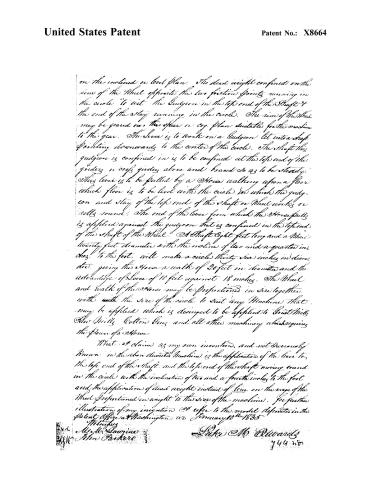 Page 3
-
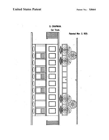 Page 4


U.S. Patent and Trademark Office · Google Patents
Show the transcription Hide (780 words)
Machine transcription (LightOnOCR) of the pages as scanned by the USPTO, most of them the handwritten copies made when the records were restored after the 1836 fire. Not checked; it can misread handwriting, so compare it with the scan.
Page 2.
United States Patent
Patent No.: X8664
Luke M Edwards. Trenton Tennessee
Letters Patent.
The Schedule referred to in these Letters Patent and making part of the same. Containing a description in the words of the said Luke M Edwards himself of his improvement in the Low and dead weight plan of Machinery.
To all whom these presents shall come.
Be it known that Luke M Edwards of Trenton, County of Gibson and State of Tennessee have invented a new and useful improvement in machinery, and that the following is a full and exact description thereof.
The Shaft of the Wheel from eight feet in length, to any length that may be required, inclined two and a quarter inches to the foot for any size Wheel, having the bottom end of the Judgon, belonging to the bottom end of the Shaft to work in a round hole in an Hub. The Judgon in the top end of the Shaft to run in a circle on a friction Roller, or confined in the end of the Lever hereafter described. The circle to be of a size sufficient to give the Shaft an incline of two and a quarter inches to the foot. The Stay with one end confined on top of the Shaft reaching one third of the way round the circle from the top Judgon confined in the Shaft with a friction Roller to the end that works in the circle, which circle is to be lined with metal to prevent its wearing. The arms of the Wheel are so fast in as to make the tops of the same always level when the shaft is moving round in any part of the circle. The Arms to be braced in the usual way of bracing them on the inclined plan. The rim of the Wheel to be fast on top of the arms, and trained in the usual ways of training Wheels either
Page 3.
United States Patent
Patent No.: X8664
on the inclined or level plan. The dead weight confined on the rim of the Wheel opposite the two friction points running in the circle "to act" the Gudgeon in the top end of the Shaft & the end of the Stay running in the circle. The rim of the Wheel may be geared on a spur or cog. plan suitable for the machine to the gear. The Lever is to work on a Gudgeon let into a shaft pointing downwards to the center of the circle. The Shaft the gudgeon is confined in is to be confined at the top end of the guider or orfs guider above and board so as to be steady. This lever is to be pulled by a Horse walking upon a floor which floor is to be level with the circle in which the gudgeon and stay of the top end of the shaft or Wheel works or rolls round. The end of the lever from which the Horse pulls is applied against the gudgeon that is confined in the top end of the Shaft of the Wheel. A Shaft eight feet long and a Wheel twenty feet diameter with the incline of two and a quarter inches to the foot. will make a circle thirty six inches in diameter giving the Horse a walk of 20 feet in diameter and the advantage of Lever of 10 feet against 18 inches. The Wheel and walk of the Horse may be proportioned in size together with the size of the circle to suit any Machine that may be applied which is designed to be applied to Grist Mills, Saw Mills, Cotton Gins and all other machinery which requires the Power of a Horse.
What I claim as my own invention, and not previously known in the above described Machine is the application of the lever to the top end of the shaft, and the top end of the shaft moving round in the circle with the inclination of two and a fourth inches to the foot and the application of dead weight instead of lever on the verge of the Wheel proportioned in weight to the size of the machine. For further illustration of my invention I refer to the model deposited in the Patent Office at Washington in January 10th 1835
Witnesses
Mr. Mr. Lawrence 3
John Parker 3
Patentee Mr. Edwards
744 no
Page 4.
United States Patent
Patent No.: X8664
S. CHAPMAN.
Car Truck.
Patented Mar. 2, 1835.

Published accounts: journal notice
Notice in the monthly list of patents, with remarks
Journal of the Franklin Institute, new ser., vol. 16 (1835), p. 230 · View the page
5. For a Lever and Dead Weight Propelling Machine; Luke M. Edwards, Gibson county, Tennessee, March 2.
Remarks. There is some ingenuity in the contrivance of this affair, but, unfortunately, the whole praise due to it ends there, as a worse arrangement for the application of animal power to drive machinery could not well be devised by the most inverted intellect. A lever, or sweep, is to be drawn round by a horse in the ordinary way, and is to turn a shaft which carries a spur wheel, the teeth of which take into a lantern, or wallower. The sweep and horse walk are above the large spur wheel, and work upon a pin descending from the top of the building, being altogether detached from the shaft of the main wheel. This shaft has a gudgeon at its lowerend working in a step; the shaft itself, however, does not stand vertically, but is inclined from the perpendicular two and a quarter inches to the foot, and the main spur wheel, which is to stand horizontally, is attached to the shaft at the same inclination, and with a corresponding eccentricity. The upper gudgeon of the shaft is made very long, and, instead of running in a box, bears against the side of a circular hole, or opening, in the centre of the floor upon which the horse is to walk, which hole is of such size as will admit of the spur wheel standing horizontally. The lever, or sweep, bears against the gudgeon, or prolonged shaft, and pushes it round. The axis travels, therefore, not like that of the earth in its annual orbit, but, although somewhat faster, like the same axis in causing the precession of the equinoxes, and, by this intricate and queer contrivance, the spur wheel preserves its horizontality, and its periphery revolves in a circle. A "dead weight is to be placed on the rim of the spur wheel," which is to operate we know not how, unless it be to keep the upper gudgeon in contact with the periphery of the hole above named. The patentee has some notion of a gain of power from this arrangement, but we are unable to perceive in what way he has reasoned to deceive himself, although it is manifest that he has effectually done So. The following is his claim. "I claim the application of the lever to the top end of the shaft, and the top end of the shaft moving round in the circle with an inclination of two and a fourth inches to the foot; and the application of dead weight, instead of lein, [?] on the virge of the wheel."
About this record
- Patentee
- DATAMP
- Date
- the Name and Date index of patents, DATAMP, USPTO records
- Invention
- DATAMP
- Listed in
- the Name and Date index of patents, DATAMP, USPTO records, Jim Shaw's X-patent list, the Journal of the Franklin Institute, Burke's List of Patents (1847)
- The Franklin Institute's journal spells the name differently.
- Burke's 1847 Patent Office list gives the same patent.