

Drawings and documents
USPTO scan
The patent as scanned by the USPTO
-
 Page 1
-
 Page 2
-
 Page 3
-
 Page 4
-
 Page 5


U.S. Patent and Trademark Office · Google Patents
Show the transcription Hide (1,343 words)
Machine transcription (LightOnOCR) of the pages as scanned by the USPTO, most of them the handwritten copies made when the records were restored after the 1836 fire. Not checked; it can misread handwriting, so compare it with the scan.
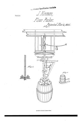
Page 1.
8665X
Printed Specification Available
J. Kinman,
Flour Packer.
Patented Mar. 2, 1835.
Fig. 1
Fig. 2
Fig. 3
AM. PHOTO-LITHO. CO. N.Y. (OSBORNE'S PROCESS)
Page 2.
Mar. 2, 1835
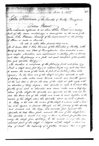
John Kiernan of the Township of Hartley, Pennsylvania
Letter Patent.
The schedule referred to in these Letters Patent and making part of the same containing, a description in the words of the said John Kiernan himself of his improvement in the packing of flour in casks or barrels.
To all to whom these presents shall come,
Be it known that I John Kiernan of the Township of Hartley in the County of Union and State of Pennsylvania, have invented a new and useful Machine and improvement in packing flour in barrels and that the following is a full and exact description of the construction and operation thereof.
The Machine is composed of the following parts and pieces viz:
First a shaft seven feet long (or whatever length may suit best, best to answer the works of the mill, to put it in motion) three inches square. In the lower end of this shaft are four spindles or axles of hickory or other solid wood turned round and smooth square at the end that is let into the sides of the shaft at right angles with an elevation of thirty degrees, each spindle or axle to be about three fourths of an inch in diameter and seven inches and a half long clear of the shaft—the spindles are squared at the ends and let into the lower end of the shaft, and made to meet together in the centre of the shaft, above the spindles about an inch or further.
A burr is let into the centre of the shaft, & a screw with a head an inch square is passed through at the joining of the spindles and screwed into the burr, and screwed fast against the spindles to keep them fast, around the end of the shaft below the spindles a small iron ring or band is placed for further securing the shaft from splitting. In the middle or any other convenient part of the shaft is slipped on the shaft a short iron box of about the capacity of a gallon measure that a weight-
Page 3.
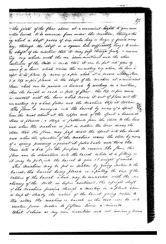
may be placed in when found necessary. The shaft may be made eight square from the lower edge of the box to the lower end if thought proper. On the spindle or axles are placed four rollers of a conical form of equal size five and a half inches in length, the inner end three inches in diameter, and the outer end eight inches in diameter, the holes in the rollers to be made through the center and of sufficient size that they may turn freely on the spindle. These rollers may be made of solid wood or metal, they may be made round or eight or sixteen sides. In the lower end of the shaft at one of the sides between any two of the rollers, a piece of iron or hickory wood is fastened by means of a hole in the shaft to lay horizontal to the shaft, the edge of this iron or piece of wood is elevated for the purpose of leveling down the flour, when the machine is in operation. On the upper end of the shaft is a block with a pulley in it fastened to the shaft, by a swivel to this block is attached a small rope which is turned over another block and pulleys attached to the upper floor or joist of the mill, when the rope is placed through the pulleys a small weight is attached to the rope, that it may slide freely along the rope, the other end of the rope is fastened to some convenient place and while the cake is filling with flour the machine is rising in the barrel the weight on the rope keeps it tight that it may not entangle with the machinery, when the barrel is full the rope is hooked on to the pin which keeps up the machine while the barrel is removing and another is put in its place. Between the block and the swivel a wooden pin passes through into a mortice cut in an upright plank, or strong board placed on the frame of the machinery and fastened to the joist or floor above to keep the block and rope from turning while the machine is in operation. This machine is put in motion in the following manner, a small cog wheel from eighteen inches to two feet in diameter is placed in a frame attached
Page 4.
the joints of the floor above at a convenient height to give room to the barrel to be removed from under the machine, through this cog wheel a shaft passes of six inches long or longer if found necessary, through this shaft is a square hole sufficiently large to receive the shaft of the machine that it may pass through freely a connecting cog wheel with the one above mentioned and the other machinery of the Mill is made that it can be put into gear by means of a lever which raises the connecting cog wheel, the lever is left to its place by means of a pin which it is passed under, there is a tap or pin placed in the shaft of the machine at a convenient place which can be raised or lowered by working in a mortice, when the barrel or cask is full of flour, this tap or pin comes in contact with the lever which moves it out of place and the connecting cog wheel falls and the machine stops its motion.
The flour is conveyed into the barrel by means of a spout from the meal chest at the upper end of the spout a board or slide is placed, a strap is fastened from the slide to the lever and when the machine is put in motion the lever draws the slide that the flour may pass down the spout into the barrel and when the operation of the machine ceases the slide by means of a spring pressing against it falls back and turns the flour into a box for the purpose to receive the flour, this flour can be shovelled into the barrel while it is filling or it may be put into the barrel to give it weight if wanted.
This machine may be put in motion by giving motion to the barrel, the barrel being placed on a pulley the size of the bottom of the barrel which may be connected with the machinery of the Mill as before mentioned, the upright shaft of the machine passing through a mortice in a plank above to keep it steady the motion of the barrel giving motion to the roller the machine or barrel as the case may be is to revolve from twelve to fifteen times a minute.
What I claim as my own invention and not previously known
Page 5.
is the machine for packing flour as described, in connection with the machinery for putting it in motion, and that will have to say according to the situation of the machinery of the mills in which it is placed. The advantage resulting from the use of this machine over the old method of shovelling the flour into the barrel from the meal chest packing with the shovel while filling, rolling it to the top which frequently requires two persons to press it sufficiently together with the waste of flour which is considerable in mills where such business is done, will be very considerable.
Witness my hand the thirty first day of January A.D. one thousand eight hundred and thirty five.
(Metropis)
James Madden
James Payne
John Riddell
(1296/10085)
(Granted 22 March 1835)
About this record
- Patentee
- DATAMP
- Date
- the Name and Date index of patents, DATAMP, USPTO records
- Invention
- DATAMP
- Listed in
- the Name and Date index of patents, DATAMP, USPTO records, Jim Shaw's X-patent list, Burke's List of Patents (1847)
- Burke's 1847 Patent Office list gives the same patent.