

Drawings and documents
USPTO scan
The patent as scanned by the USPTO
-
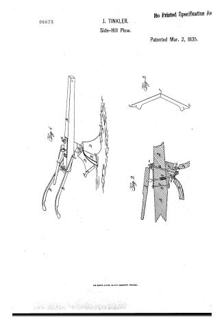 Page 1
-
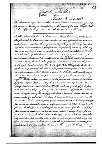 Page 2
-
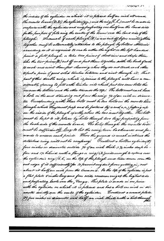 Page 3
-
 Page 4
-
 Page 5


U.S. Patent and Trademark Office · Google Patents
Show the transcription Hide (1,604 words)
Machine transcription (LightOnOCR) of the pages as scanned by the USPTO, most of them the handwritten copies made when the records were restored after the 1836 fire. Not checked; it can misread handwriting, so compare it with the scan.
Page 1.
8667X.
J. TINKLER.
Side-Hill Plow.
No Printed Specification Av
Patented Mar. 2, 1835.
Fig. 1.
Fig. 2.
Fig. 3.
A.M. PHOTO-LITHO. CO. N.Y. (OSBORNE'S PROCESS).
Page 2.
Joseph Tinkler
Letters Patent
(Patented March 2, 1835.)
The Schedule referred to in these Letters Patent and making part of the same containing a description in the words of the said Joseph Tinkler himself of his improvement in the construction of Ploughs
To all to whom these presents shall come, Be it known that I the said Joseph Tinkler have invented constructed and applied to use new and useful improvements in the art of constructing Ploughs. The Plough containing said improvements is specified in the following words viz: Take any two common ploughs made in such form and of such materials as will best suit the wishes of the Farmer on the section of country where it may be introduced, which must be constructed as nearly as the skill of the mechanic will admit, but with the exception that the one must turn the plow to the right hand and the other to the left. (D,D.) Then fasten the two together in one piece with the shares (C,C) or points turned opposite to each other in such a manner that the land side r.s.l. of the two will exactly range which are also joined in one piece on an angle of one hundred and twenty-eight degrees. So that when one point is in the ground the other will be elevated fifty two degrees. Before uniting the two mould boards together it will be necessary to cut a considerable portion (B) of the back end of each off for the purpose of rendering the plough as light and convenient as possible but in no case must the upper ends of the two (g,g) (on the land side) come nearer than six or seven inches of each other. The space between will form an angle where the two meet. Within this angular space must be placed a hollow cylinder (g,g) five inches in diameter inside and of a convenient depth for the height of the plough. On the upper end of this cylinder is placed a cylindrical ring (h,h) four inches in diameter inside and seven outside leaving the size of it one and a half inches the thickness must be half an inch. The upper side of this ring must be so placed that when a line is extended from it both ways over each point (d,d) and level with it that the perpendicular distance from each point to the line will be the same. This ring will then project over the
Page 3.
the inside of the cylinder on which it is placed half an inch all round. The mould board (D.D.) the cylinder (g.g.) and the ring (h.h.) must be made in one piece with the cylinder and ring projecting one half over the land side for the purpose of placing the centre of the beam over the land side of the plough. So much of each plough (E) as was cut off before uniting them together may be alternately attached to the plough by bolts or otherwise according as it is required to make either the right or the left handed point a full plough, or take two pieces of sheet iron and shape them like the two pieces (E) out off and put them together with the back of each to each and rivet them fast observing where they do not touch each other to put a piece of good solid timber between and rivet through it. That part of this double ring which is joined to the plough will have a considerable opening to fill with timber into which put two screw bolts the one near the bottom and the other towards the top. The bolts must each have a hole in the end standing out from the ring 3/8 of an inch in diameter. Corresponding with these bolts must be two holes in the mould board through which they must pass and be fastened by a rod (e.e.) passing up on the inside of the plough exactly where the two meet together. This bolt must be kept to its place by holes through two lugs projecting from the back side of the mould board. The holes through the mould board must be sufficiently long to let the ring turn backwards and forwards to answer each point. Where the ground is much inclined the detached ring will not be necessary. Construct a hollow cylinder (R) four inches in diameter outside 3/8 of an inch thick 3 3/4 inches deep before and 1 1/4 behind with a flange or ring (i.k.) wide enough to extend over the cylindrical ring (h.h.) on the top of the plough and turn down over the out edge of it sufficiently far to prevent any dirt from getting in just about it half an inch from the lower end. On the top of the cylinder is put a flat plate 8 inches long and four wide commencing at the highest side and projecting back over the flange. This plate is made in one piece with the cylinder on which it is placed and has a hole one inch in diameter directly over the centre of the cylinder. Construct a round plate (P) five inches in diameter and half an inch thick with a hole through the
Page 4.
the centre one inch in diameter. This plate is put on the inside of the neck (g,g,) of the plough (a cylinder made fast to it) as far as the wing (h,h) projecting over will permit. At there meets the lower end of the last described cylinder (E) and is fastened to it by a bolt (x) passing through both. There must be a big cavity in each side of the round plate (R) exactly where the end of the cylinder (E) meets it with corresponding niches in the lower end of the cylinder to prevent the one from turning without the other. The bolt passing down through the cylinder (E) passes up through the beam (A) and fastens it by a nut (m,) above to the plate on the top of the revolving cylinder (E). Another bolt (Q) of an inch thick passes up through the lower end of the same plate and beam to prevent it from turning without the cylinder. A pin (T,) of an inch in diameter passes down through the beam a little forward of the last mentioned bolt (Q,) and through the flange (e,k,) in the cylinder into the neck of the plough to prevent it from turning while in the act of ploughing). This pin is raised or drawn up by a lever (L,) attached to the upper end of it. In order to ensure the entering of the pin (T,) in turning without the help of the plough man a spiral or other spring (y) is attached to it. The handles (B,B,) are fastened to the beam by two flat rods of iron one (c,) 5 inches between the tenons with a hole through centre passing transversely through the lower part of the beam. The small bolt (z,) which passes up through the plate and beam, passes through it, and keeps it to its place. The other (a,) is 12 1/2 inches between the tenons and has a slit in the centre 6 inches in length and is fastened to the upper side of the beam near the hind end, or sufficiently far back to give the handles a proper elevation, by a screw bolt (b,) passing down through the slit. This rod (a,) is curved to correspond with the use of a circle described by a radius equal to the distance between the two rods (a,b,c). The handles (B,B,) are fastened to the tenons and may be moved to either side by the bolt (b,) and slit to suit the plough hand. The above described plough is designed for both a hill side and flat land plough. It may be used as a common or double plough. The method of turning or changing it from front to front is simply at the one instead of going
Page 5.
522.
for Rules to my knowledge consists as follows. The common joint is composed of two or a few pieces of metal which when placed together form a solid shape of the thickness of the Rule and is attached to the Ruler or other material composing the Legs of the Rule by removing a portion of their thickness to receive the joint which diminishes their strength. The joint possesses little or no elasticity consequently as it wears it becomes loose. My improved joint is applied to the Rule without removing any of its thickness to receive it which is one of the principles I claim as my invention.
The manner of forming the joints of thin plates attached to the sides of the two legs, the intervening space being filled with the substance of the Rule itself, instead of the more expensive mode of filling that space with metal is another principle I claim as my invention. My joint then formed and applied possesses a degree of elasticity operating as a perpetual Spring which prevents the joint from ever becoming loose.
Samuel Hedge
Exh. Witnesses
Wm. M. Clark
John Holland
Drawing made: 6.15 m.d.
Published accounts: journal notice
Notice in the monthly list of patents, with remarks
Journal of the Franklin Institute, new ser., vol. 16 (1835), p. 229 · View the page
3. For a Plough; Joseph Tinkler, Warwick, Tuscarawas county, Ohio, March 2.
Remarks. This machine is rather complex, as it is to consist of two perfect ploughs, united together, and attached to the same beam; these ploughs are to be brought alternately into use, and, to effect this, the beam must be shifted at the end of the furrow, in a manner described in the specification. "The plough is designed for both a hill side and flat land plough. It may be used as a common, or double, plough. The method of turning or changing it from point to point, is simply, at the end, instead of going round a piece of ground in the usual way, raise the pin, and when it is up, turn your team, and when the beam has moved a little way from its place, you may let go the lever, and when it is sufficiently round, the pin will drop into a hole in the opposite side of the neck. In turning, the point that was in the ground rises, and the other falls, when you may return by the same furrow which you came." "That part of the plough which I claim as my invention, is the combination of two perfect common ploughs in one, with the point of one elevated, whilst the other is in the ground; the revolving neck, and the principle of moving the handles from side to side, at pleasure." We have not attempted to give a particular description of the arrangements by which the object in view is to be attained, as this could scarcely be done without a plate. Double ploughs, with shifting beams, have been patented, but the manner of attaching them, and the auxiliary arrangements, as presented to us in the specification before us, differ materially from any which have been heretofore adopted.
About this record
- Patentee
- DATAMP
- Date
- the Name and Date index of patents, DATAMP, USPTO records
- Invention
- DATAMP
- Listed in
- the Name and Date index of patents, DATAMP, USPTO records, Jim Shaw's X-patent list, the Journal of the Franklin Institute, Burke's List of Patents (1847)
- Burke's 1847 Patent Office list gives the same patent.