

Drawings and documents
USPTO scan
The patent as scanned by the USPTO
-
 Page 1
-
 Page 2
-
 Page 3


U.S. Patent and Trademark Office · Google Patents
Show the transcription Hide (804 words)
Machine transcription (LightOnOCR) of the pages as scanned by the USPTO, most of them the handwritten copies made when the records were restored after the 1836 fire. Not checked; it can misread handwriting, so compare it with the scan.
Page 1.
No Printed Specification Available
8682X
R. Eastman,
Water Wheel,
Patented Mar. 11, 1835.
Fig. 2.
Fig. 3.
Fig. 1.
Page 2.
May 11, 1835
Robert Eastman, of Concord, N.H. 8682X
Letters Patent.
The schedule referred to in this Letters Patent, and making part of the same containing a description, in the words of the said Robert Eastman, himself, of his improvement in the construction of Water Wheels.
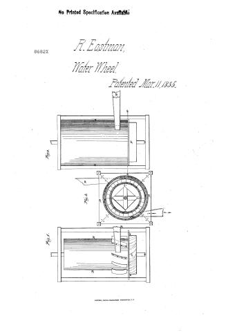
To all whom it may concern; Be it known that I Robert Eastman of Concord in the County of Merrimac, and State of New Hampshire, have invented certain improvements in the construction of the water wheel used for driving machinery by the combined action of using the water by percussion and reaction on the same wheel, which combination produces more power from the same quantity of water than has heretofore been obtained by the application of either of these methods separately. And I do hereby declare that the following is a full and exact description of my said improvement, reference being had to the drawings which accompany and make part of these specifications. This wheel may be constructed of cast iron when wanted for permanent works; or for cheapness in common mills it may be made principally of wood with iron floats or buckets, and may be constructed as follows: When made of wood the shaft must have a cylinder to extend from the bottom of the shaft to the summit height of the water in the flume, where the head and fall is not very large. This cylinder for a common grist mill where there is eight or ten feet head may be about three and half feet in diameter. The bottom end of this cylinder is made conical where the reacting floats are attached so as to contract the water and bring the discharge as near the periphery of the wheel as possible. These buckets should be about six inches wide at the top, and about three or four inches at the bottom, and twelve in depth, nearly in the form of a common tail wheel only the buckets are placed nearer together, and more curving at the bottom. On the outer edge of these floats, I place a rim of staves and secure them by iron hoops, the upper ends to be turned off true to fit into the planking as shown in the drawing at A.A., Fig. 3. These planks are secured firm in four upright posts, and the circle cut to fit the part turned off so that the wheel can turn without much friction. Directly above the reacting floats I place the percussion floats as shown in the drawing, these may be fewer in number and about twenty inches deep and six wide.
Page 3.
bolted firm in the cylinder. I then surround the wheel with a cylinder or covering that rest on plank D.D. and extending to the top of the cylinder on the wheel, and large enough to clear the outer edges of the percussion floats two or three inches. A covering is made inside of the stationary cylinder from one spout to the other as shown at S.S. in the drawing to drive the water against the percussion floats more uniformly. I then apply the water by a conductor as shown in the drawing which should extend as near the floats as can without touching them. When the water is thus applied it partakes of a rotary motion and acts on all the floats at the same time and being confined by the outer cylinder rim, to nearly the summit height of the water in the floor, and the head thus raised in the cylinder acts on the bottom floats by its gravity and produces a reacting power as it leaves the wheel and the action of one part does not appear to retard the action of the other, and by this combining the several powers on one wheel a much greater power is obtained from the same water than has heretofore been derived, and the cylinder prevents the back water from affecting the percussion floats, so that it will operate in back water as well as any reacting wheel. Where the wheel wants to be extended for large works it may be made much larger in diameter and more spouts added. What I claim as my invention and for which I ask a patent is, the combined arrangements in the above described water wheel, I also claim any other form in which they may be put to produce the same result.
Witnesses:
Jonathan Eastman Jr.
Sarah E. Eastman
Robert Eastman
(Drawing)
Typ.
M.G.
Published accounts: journal notice
Notice in the monthly list of patents, with remarks
Journal of the Franklin Institute, new ser., vol. 16 (1835), p. 237 · View the page
24. For an improvement in the construction of Water Wheels; Robert Eastman, Concord, Merrimack county, New Hampshire, March 11.
Remarks. The patentee calls this a "combined percussion and reacting wheel." There is a stationary cylinder which stands vertically, and within this is a second cylinder, less than the former, and fixed on gudgeons to revolve within it. On the lower end of this second cylinder is the reacting wheel, made in the form of Wing's and other reacting wheels; it has its upper edge even with the ordinary surface of the water in the river, or tail race, and fitting closely against the lower edge of the stationary cylinder. Above this reaction wheel there are floats on the revolving cylinder, extending upwards, and upon these the water is to strike on being admitted through a conductor, or trunk, opening through the stationary cylinder for that purpose. The water, it is said, will rise nearly to the height of the head in the space between the two cylinders, and thus act by its gravity upon the reaction wheel, with little or no loss of effect upon the percussion floats. The claim is to the before described arrangement.
DATAMP: illustration
Illustrations from DATAMP

DATAMP (Directory of American Tool and Machinery Patents), via the Internet Archive · Archived DATAMP page
About this record
- Patentee
- DATAMP
- Date
- the Name and Date index of patents, DATAMP, USPTO records
- Invention
- DATAMP
- Listed in
- the Name and Date index of patents, DATAMP, USPTO records, Jim Shaw's X-patent list, the Journal of the Franklin Institute, Burke's List of Patents (1847)
- Burke's 1847 Patent Office list gives the same patent.