

Drawings and documents
USPTO scan
The patent as scanned by the USPTO
-
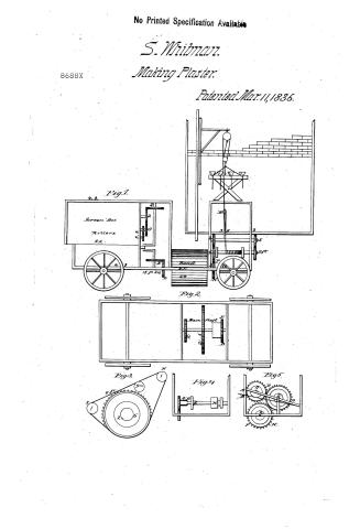 Page 1
-
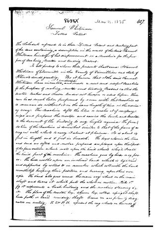 Page 2
-
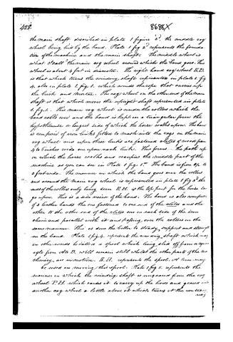 Page 3
-
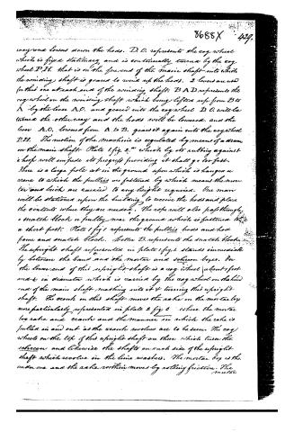 Page 4
-
 Page 5
-
 Page 6


U.S. Patent and Trademark Office · Google Patents
Show the transcription Hide (1,906 words)
Machine transcription (LightOnOCR) of the pages as scanned by the USPTO, most of them the handwritten copies made when the records were restored after the 1836 fire. Not checked; it can misread handwriting, so compare it with the scan.
Page 1.
No Printed Specification Available
S. Whitman
Making Plaster.
Patented Mar. 11, 1836.
8688X
Fig. 1.
Screen Box
Motters.
R.C.
Fig. 2.
Main Shaft
Fig. 3.
Fig. 4.
Fig. 5.
Page 2.
8688X Mar 11, 1835 427.
Samuel Whitman
Letters Patent
The Schedule referred to in these Letters Patent and making part of the same containing a description in the words of the said Samuel Whitman himself of his improvement in a machine for the purpose of making mortar and tending Masons.
To all persons to whom these presents shall come, Samuel Whitman of Danville in the County of Vermilion and State of Illinois sends greeting. Be it known that the said Samuel Whitman (and controlled) have invented and made a new and useful machine for the purpose of making mortar and tending Masons called the mortar maker and Mason tender not known or used before. There can be as much labor performed by 3 men with this machine as 12 men can do without it in the same length of time in the ordinary way. The machine lifts the lime or washes it if necessary, mixes and prepares the mortar and carries the brick and mortar to the summit of the building to any height required. The foundation of the machine is somewhat similar to that of the frame of a wagon with wheels to carry it about at pleasure. It is about 14 feet in length and 6 feet in breadth. The boys wherein the lime and sand are sifted and mortar prepared are placed upon that post of the foundation which rests upon the hind wheels which scall the hind part of the machine. The machine goes by horse or power. The horse walks upon an inclined band which is lighted and supported by rollers & in number which roll with the band nevertheless keeping their position and turning upon their own axis. The band also goes round the main cog wheel on the main shaft and turns it which puts the whole in motion. Plate 1st fig 1st represents a brick building and the machine standing by it. The place of the mortar boy, screen boy, rollers, upright shaft, horse path or band, revolving shaft, crane &c are plainly designated in writing. B. L. & P. L. represent the cog wheels on the ends of the
Page 3.
the main shaft described in plate 1 figure 2. the middle cog wheel being hit by the band. Plate 1 fig 2 represents the foundation of the machine and the main shaft. The middle wheel is what I call the main cog wheel around which the band goes. This wheel is about 4 feet in diameter. The right hand cog wheel B.B. is that which turns the winding shaft represented in plate 1 fig 4. also in plate 1 fig 1. which winds the rope that carries up the brick and mortar. The cog wheel on the other end of the main shaft is that which moves the upright shaft represented in plate 1 fig 1. This main cog wheel is under the rollers which the band rolls over and the band is kept in a triangular form the hypotenuse or longest side of which the horse walks upon. The band is composed of iron links fitted to mesh into the cogs on the main cog wheel and upon these links are fastened slats of wood from 4 to 6 inches wide one upon each link. This forms the path upon which the horse walks and occupies the middle part of the machine as you can see in Plate 1 fig 1. The band is from 2 to 3 feet wide. The manner in which the band goes over the rollers and around the main cog wheel is represented in plate 1 fig 3 the ends of the rollers only being seen B.B. is the top part for the horse to go upon. This is a side view of the band. The band is also composed of 2 leather bands the one fastened to one end of the slats and the other to the other end of the slats one on each side of the iron chain and parallel with it and passing over the rollers in the same manner. This is done the better to steady, support and strengthen the band. Plate 1 fig 4. represents the winding shaft which may in other words be called a spool which being slid off from a square axle from A to B. will remain still whilst the other parts of the machinery are in motion. B.B. represents the spool. A lever may be used in moving this spool. Plate 1 fig 5. represents the manner in which the winding shaft is unspooled from the cog wheel P.P. which causes it to carry up the horse and geared into another cog wheel a little above it which turns it the contrary way.
Page 4.
way and lowers down the hoard. D. O. represents the cog wheel which is fixed stationary and is continually turned by the cog wheel P. H. that is on the fore end of the main shaft into which the winding shaft is geared to wind up the hoard. 2 levers are used for this one at each end of the winding shaft. B A D. represents the cog wheel on the winding shaft which being lifted up from B to A by the lever A. O. and geared into the cog wheel D. O. will be turned the other way and the hoard will be lowered, and the lever A. O. lowered from A. to B. gears it again into the cog wheel P. H. The motion of the machine is regulated by means of a drum on the main shaft. Plate 1. fig. 2. wheels by its rubbing against a hook will impede its progress providing it shall go too fast. There is a large pole set in the ground upon which is hanged a crane to which the pulleys are fastened by which means the mortar and brick are carried to any height required. One man will be stationed upon the building to receive the hoard and place the contents where they are needed. The rope will also pass through a snatch block or pulley near the ground which is fastened to a short post. Plate 1 fig 1 represents the pulleys hoard and hoard frame and snatch block. Letter B. represents the snatch block. The upright shaft represented in plate 1. fig. 1. stands immediately between the band and the mortar and screen box. On the lower end of this upright shaft is a cog wheel about 1 foot over in diameter which is carried by the cog wheel on the hind end of the main shaft meshing into it & turning this upright shaft. The crank on this shaft moves the rake in the mortar box more particularly represented in plate 2 fig 6 where the mortar box rake and crank and the manner in which the rake is pulled in and out as the crank revolves are to be seen. The cog wheels on the top of this upright shaft are those which turn the screen and likewise the shafts on each side of the upright shaft which revolve in the line washers. The mortar box is the under one and the rake within moves by rolling friction. The mortar
Page 5.
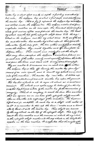
mortar box is about 2 feet and ½ in depth 5 feet long and about 4 feet wide. The screen box is about 3 feet deep and directly over the mortar box. Plate 2 fig 7 represents the screen box and screen and rollers under the screen box. The screen or sieve is in form a cylinder revolves on its own axis. The lime and sand are put inside of it and are sifted and fall into the mortar box. The breast cog wheel near the top of the upright shaft turns D.B. the cog wheel on the screen and this cog wheel turns B.H. one of the rollers and this roller has another cog wheel upon it that turns the other roller by the side of it. The two rollers are placed directly under the screen they mesh together and the lime falls in between them. These mesh and make fine all the lumps that may have escaped the screen. 2 inclines planes one on each side of the rollers nearly meet exactly between the rollers and draw the lime and sand into a very small compacts. They are nailed to 2 concaves one on each side of the rollers. The screen box is slid off leaving the mortar box open by means of an iron crank and 2 small cog wheels one on each side of the machine. The mortar box can then be tilted up and the contents emptied into another box upon the ground. This box has wheels to it to move it about as is most convenient. The wheels and axles may be taken off from this box and this box placed inside of the mortar box for the convenience of carrying. When it is necessary to wash the lime there are 2 boxes that are square one on one side of the upright shaft and the other on the other side opposite ways of the machine. The boxes are 2 feet and ½ in depth. In each box is a shaft with cakes up on it 3 in number to stir up the lime water and a tunnel also to lead it into the mortar box. These shafts are turned by the cog wheel on the top of the upright shaft. Plate 2 fig 8 represents the lime washers and the manner in which the cog wheel on the upright shaft meshes into the cog wheels on the shafts that revolve in the lime washers. It is expected that the weight of the
Page 6.
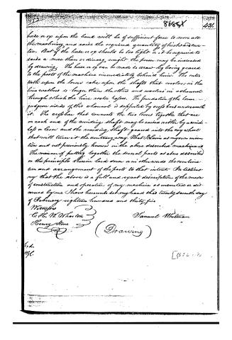
horse or op upon the band will be of sufficient force to move all the machinery and raise the required quantity of bricks and mortar. But if the horse or op should be too light or it be required to raise a more than ordinary weight the power may be increased by drawing. The horse or op can be made to draw by being geared to the posts of the machine immediately behind him. The roller rests upon the lower rake upon the shafts that revolve in the line washers. The longer than the others and revolves in a channel through which the line roller passes. The foundation of the lower guide on sides of this channel is supported by cross bars underneath it. The cross bar that connects the two levers together that are on each end of the revolving shaft may be raised either by a windlass or lever and the revolving shaft geared into the cog wheel that will turn it the contrary way. What I claim as my own invention and not previously known in the above described machine is the manner of putting together the several parts as above described on the principle therein laid down or in other words the combination and arrangement of the parts to that intent. In testimony that the above is a full and exact description of the mode of construction and operation of my machine as invented or discovered by me I have hereunto set my hand this twenty seventh day of February eighteen hundred and thirty five.
Witnesses
C. H. W. Wharton
Henry Stone
(Drawing)
Published accounts: journal notice
Notice in the monthly list of patents, with remarks
Journal of the Franklin Institute, new ser., vol. 16 (1835), p. 238 · View the page
27. For a Mortar Mixer and Mason Tender; Samuel Whitman, Vermillion county, Illinois, March 11.
Remarks. A carriage, having a resemblance to a wagon body, is to be placed upon wheels in order to move it from place to place; it may be about fourteen feet long, and six wide. Attached to it there is an inclined movable floor, upon which a horse, or other animal, may walk in order to give motion to the machinery, which consists of boxes, wherein the lime and sand are placed and sifted; a rake, moved by a crank, for mixing the mortar; pulleys and tackle for raising hods to the top of the building, and certain other appendages which may be required. The claim made is to "the manner of putting together the several parts as above described, on the principle laid down; or, in other words, the combination and arrangement of the parts." Such a description and claim as form this specification, if they secure any thing, cannot embrace more than the particular arrangement adopted by the patentee, as there is not any thing new in the individual parts, and as analogous combinations have been repeatedly made.
About this record
- Patentee
- DATAMP
- Date
- the Name and Date index of patents, DATAMP, USPTO records
- Invention
- DATAMP
- Listed in
- the Name and Date index of patents, DATAMP, USPTO records, Jim Shaw's X-patent list, the Journal of the Franklin Institute, Burke's List of Patents (1847)
- Burke's 1847 Patent Office list gives the same patent.