

Drawings and documents
USPTO scan
The patent as scanned by the USPTO
-
 Page 1
-
 Page 2
-
 Page 3
-
 Page 4


U.S. Patent and Trademark Office · Google Patents
Show the transcription Hide (1,071 words)
Machine transcription (LightOnOCR) of the pages as scanned by the USPTO, most of them the handwritten copies made when the records were restored after the 1836 fire. Not checked; it can misread handwriting, so compare it with the scan.
Page 1.
8689X
W. E. Arnold,
Horse Power.
Patented Mar. 13, 1835.
Fig. 1.
Fig. 2.
Fig. 3.
Fig. 4.
AM. PHOTO-LITHO. CO. N.Y. (OSBORNE'S PROCESS)
Page 2.
William E. Arnold, of Chatham, Conn. 8689X
Letters Patent
The Schedule referred to in these Letters Patent and making part of the same, containing a description in the words of the said William E. Arnold himself of his improvement in a Horse power.
To all persons to whom these presents shall come: Be it known that I William E. Arnold of Chatham in the County of Middlesex and State of Connecticut have invented, made, constructed and applied to use a new and useful improvement in the machine for applying horse and other animal power to sundry mechanical purposes not known or used before this my said discovery which I specify and describe in the words, figures and references following to wit: — The length and breadth of the machine is suited to accommodate the horse or horses or other animal or animals standing thereon to work it, say for a one horse machine, let it be about ten feet long by two feet wide or of any other size. Its side planks are secured together by by firm cross pieces. Between these side planks are three cylinders or trundles; one at letter A, one at B, and one at C as represented in fig. 1 of the drawing accompanying this description, the pivots or guidons of which run into or through the above mentioned side planks, on the circumference of these cylinders are fixed several half circle cambs as represented by figure 3. The floor of the machine (on which the animal stands) is constructed of strips of wood or iron which I shall call slats so thin that the foot of a horse will cover 3-4 or more of them at one time. Every other slat in this floor is secured & framed together in one frame so as to make but one motion when it moves backward or forward & every of the remaining slats constituting another frame for another motion, all which is represented in fig. 2, letters A & B except several cross pieces underneath which are not seen in the drawing. These two frames rise and fall alternately (when the machine is running) by meeting the half circular cambs before mentioned on the revolving cylinders under the floor. Two slats extend from each of the above mentioned frames along each side of the eccentric or cambs wheels D and E and beyond them. On the ends of each pair of these extended slats are three little rollers, the middle one of which in each pair by pressing against the periphery of the cambs wheel while the horse draws (commencing at point A, in fig. 4) gives it motion in the direction of
Page 3.
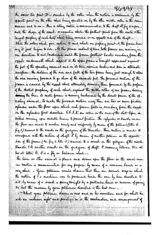
the same till point B is reached by the roller when the motion is continued by the opposite point on the other wheel being operated on by the other middle roller in the same manner and so on — Thus a rotary motion is communicated to the shaft F, fig. 4 or pre- huts, the shape of the cam or eccentric wheels, the farthest points from the center & the largest periphery of each half wheel being reversed or on opposite side of the shaft. While the rollers which give motion to said wheels are passing point A, the frame bearing it just begins to rise. At this precise instant of time, both frames are moving in one direction to wit, backwards, until the frame farthest back receding from the cam, underneath which support it, the upper frame is brought uppermost against the feet of the operating animal and in its turn carries back; and soon in alternate succession — the distance of the rise and fall of the two frames being just enough to allow the one moving forward to go clear of the animal’s feet. The forward motion of the frame is caused by the cam wheels, alternately drawing them forward by the pressure of the shortest periphery of each wheel, against the middle roller of one frame, during the time its mate frame is moving backwards by the direct power of the operating animal. To make the forward motion easy, there are two or more friction cylinders under the floor upon which each frame falls in receding from the cams on the cylinders first described. G, H, I, K are rollers on the ends of the slats before described running upon suitable bearings to prevent friction. The cylinders or trundles under the floor are made to revolve evenly and uniformly by means of the pitman (letter L, fig. 1) secured to the crank on the gudgeon of the trundles. Their motion is made to correspond with the motion of shaft F by means of another pitman on the opposite side of the frame (see fig. 2, letter C) secured to a crank on the gudgeon of the middle trundle & to another crank on the gudgeon of shaft F, running between two rollers at letter G. O is a fly or balance wheel —
The horse or other animal is placed and drawn upon the floor in the usual manner & motion is communicated for any purpose by means of a common band or a cog wheel — Your petitioner would observe that there are several ways in which the motion of this machine can be produced beside the one by him described to wit, by means of a crank a spring weight by a particular kind or manner of gearing &c. but the manner by your petitioner described is the best one —
What your petitioner claims as new and as his invention and for what he asks an exclusive right and privilege in, is, the combination and arrangement of
Page 4.
the several parts of his machine as herein before described, and also the new principle of a flat floor so constructed as to apply horse or other animal power upon it in producing any motion used for mechanical or other purposes—
Dated at Middletown in said County of Middlesex this 9th day of October A.D. 1834.
Witnesses
Wm. Goodrich
Saml. W. Guiswaley
William C. Arnold
(End Mfg.)
10 84 w 92
(Sealing)
Published accounts: journal notice
Notice in the monthly list of patents, with remarks
Journal of the Franklin Institute, new ser., vol. 16 (1835), p. 238 · View the page
To get up a really new churn would be no easy task, and we are not disappointed, therefore, in finding the one before us much like others which have previously passed in review. Double churns are common, but the present patentee makes the body of his an oblong square box, with two dashers, one near each end. The dasher handles are attached to a vibrating lever, supported on two standards, the vibratory motion being given by the turning of a crank shaft. A very particular description is given of all the parts; such, for example, as that the dashers are formed by two pieces of wood crossing at right angles, and halved into each other. The claims made serve to show the difficulty of pointing out any thing that is new, consisting of "the application of the standards to receive the bar which revolves between them, and in the formation of their lower ends, together with the cross wedges by which the top may be removed from the box, when these wedges are loosened." 29. For a Horse Power; William E. Arnolds, Chatham, Middlesex county, Connecticut, March 13.
Remarks. This we believe to be a new mode of applying horse power to drive machinery; it is contrived with considerable ingenuity, but this, unfortunately, is no guarantee for its practical utility. The horse is to stand upon a platform made of slats, which, instead of being placed crosswise, as they are in the endless bands, extend longitudinally upon the basis of the machine; these slats are to stand edgewise, and are to be so thin, that the foot of the horse will cover the edges of three, four, or more of them; the slats constitute parts of two sliding frames, every other one being secured to its corresponding frame. These frames rest upon a kind of cam rollers, which, with the addition of certain cam, or eccentric, wheels, cause the frames alternately to rise against the feet of the horse, and to traverse backwards and forwards. The particular arrangement by which this is to be effected we shall not attempt to describe. The claim made is to the arrangement by which this new principle of constructing a horse power, is carried into operation.
About this record
- Patentee
- DATAMP
- Date
- the Name and Date index of patents, DATAMP, USPTO records
- Invention
- DATAMP
- Listed in
- the Name and Date index of patents, DATAMP, USPTO records, Jim Shaw's X-patent list, the Journal of the Franklin Institute, Burke's List of Patents (1847)
- The Franklin Institute's journal spells the name differently.
- Burke's 1847 Patent Office list gives the same patent.