

Drawings and documents
USPTO scan
The patent as scanned by the USPTO
-
 Page 1
-
 Page 2
-
 Page 3
-
 Page 4
-
 Page 5
-
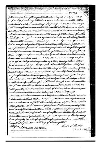 Page 6


U.S. Patent and Trademark Office · Google Patents
Show the transcription Hide (1,949 words)
Machine transcription (LightOnOCR) of the pages as scanned by the USPTO, most of them the handwritten copies made when the records were restored after the 1836 fire. Not checked; it can misread handwriting, so compare it with the scan.
Page 1.
8690X
J. S. DICK.
THRASHING, HULLING, AND SHELLING MACHINE.
Patented Mar. 13, 1835.
NO PRINTED COPY OF SPECIFICATION IN OFFICE.
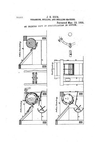
<!-- Image content: Technical drawings of a machine with labeled sections -->
Section Corn-shelling
Front Thrashing
Section Hulling
Section Thrashing
Page 2.
March 13, 1835
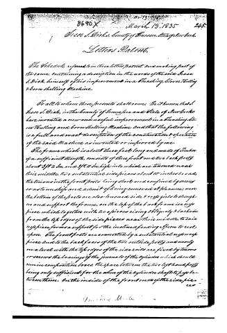
Lessee J. Dick, County of Greene, State of New York.
Letters Patent.
The Schedule referred to in these letters patent and making part of the same, containing a description in the words of the said Lessee J. Dick, himself of his improvement in a Threshing, Clover Threshing & Corn Shelling Machine.
To all to whom these presents shall come: Be it known that I, Jesse J. Dick, in the County of Greene and State of New York have invented a new and useful improvement in a Threshing, Clover Threshing and Corn Shelling Machine and that the following is a full and exact description of the construction, operation of the said Machine as invented or improved by me.
The frame which is about three feet long and made of timber of a sufficient strength, consists of three front and two back posts about 3 ft 4 in. and 3 ft 11 in. high into which are tenoned near their middle, two substantial side pieces about 10 inches broad, the tenons in the front posts being short and confined by screws so as to unship and admit of being removed at pleasure; near the bottom of the posts are also tenoned side cross pieces to strengthen and support the frame, on the top of the back frame is a cross piece which together with two pieces rising obliquely & backwards from the top edges of the side pieces near their middle, to said cross piece forms a support for the inclined feeding spoon to rest upon. The front posts are connected by a substantial cross piece and to the back faces of the two outside posts and nearly on a level with the top edges of the side rails are fixed by tenons or screws the bearings of the journals of the cylinder which should run in composition boxes, the space between the two left hand posts being only sufficient for the wheel of the cylinder shaft to pass between them. On the inside of the front ends of the side pieces
Page 3.
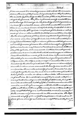
pieces are made two circular grooves into which the coneave slides; the sides of the frame being closed from the front to near the middle by planking on the inside of the side pieces extending to the ground. The fan is placed nearly under the coneave having its bearings in the planking and being covered in rear by a circular case. Also close under the coneave there is an inclined board which falls to the front that is let into the side planks. The cylinder is composed of two heads or wheels made of iron or other suitable material secured to an iron shaft. On the circumference of these heads are placed longitudinally 5 or more iron bars of say 3/8 inch iron & the intermediate spaces being filled with wooden strips or shaves of the same thickness made moveably by means of screws, the whole is bound firmly together by three iron bands, one placed at each end and one in the middle of the cylinder. Holes are made in these bars at equal distances to receive the teeth which are to range on alternate bars; these teeth are made of 1/2 inch iron in form resembling the catch of a common thumb latch having a strong shoulder and oblique side; the oblique side or edge is serrated like a saw or beaded by the strokes of a chisel with a groove or channel passing down the centre and are secured to the bars by screws on the under side, those on the extremity of each alternate bar passing obliquely through the band, bar and rim or wheel to confine the bars to their places as also do those on the middle. The coneave which is of cast iron 3/4 inch thick is one fifth of a circle with five rows of teeth standing on ribs that project 3/8 inch, four of these rows stand alternate but the fifth or bottom row has double the number, and therefore range with the teeth and spaces of the rest; these teeth are of the same form as those in the cylinder except that they are not serrated, and are made fast to the coneave by screws on the under side. The hopper consists simply of two light side pieces which rest on the feed upon already mentioned and fit close to the front posts.
Page 4.
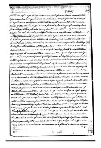
parts, the top edge being level and their front ends connected by a circular or square case which encloses that part of the cylinder contiguous thereto except a small portion near the lip of the apron sufficient for the feeding. Operation for threshing. The cylinder being put in revolution by a band from the power wheel to the pulley the sheaves are placed on the apron so that the heads pass between the cylinder and cone and the threshed grain and straw is discharged on the opposite or front side of the Machine in the usual way. For hulling the hopper. The staves of the cylinder and the cone as above described are removed, and the following parts substituted or added: To remove the cone it only being necessary to unshift the front parts of the frame. A hopper formed of a bottom piece and side pieces similar to that used for threshing except that the front is formed by the upper cone case instead of the cylinder case and the lower edges of the front ends descend to the grooves of the cone case and are shaped to coincide with them having a frame and wire or spun iron sieve fitted thereto which takes the place of the cone case just removed being of the same size. Fig. 10. of a circle on the upper sides of the two cross bars of the sieve frame rests two small metal shafts which have their bearings on the side pieces of the hopper and to the upper side of which are fixed by bracing or otherwise teeth that point towards the center of the cylinder, said shafts are also furnished with spiral springs at their extremities made fast to the side of the hopper for the purpose of permitting a partial revolution of the shafts when the teeth are engaged and to bring them again to their places. The lip of the feed apron in this hopper is a strip of iron 6 or 8 inches wide attached by hinges to the apron and causes when the Machine is in operation to vibrate rapidly by the revolution of a square shaft on which its outer edge rests. The upper cone case above mentioned commences a short distance above this
Page 5.
this lip being a segment of the same circle with the lower cone and extends to near the top edge of the of the sides of the hopper where it meets with and butts against a division board which I call the regulator that slides in grooves made in the sides of the hopper at right angles to the cone and and reaches from the cone to the upper edge of the hopper, the lower edge of this regulator is armed with strong points as also the upper and lower margins of the cone, the intermediate space of the latter being filled with shorter points made of light iron wire say 1/4 inch diameter to project 1/8 of an inch, the groove of the cone in the side pieces is continued to the ends of said pieces for the purpose of receiving a portion of a similar cone on the opposite or front side of the cylinder which may be termed the upper front section, for supporting this upper section, two perpendicular side pieces are raised of the same height as the front parts and of a width part to admit them between the inner front parts of the frame their front edges meeting the front edges of the hopper, being notched where requisite to accomplish that object in the lower part of these side pieces grooves are cut which receive and support a frame and cone in front of the cylinder precisely similar to that already described in its rear of which it is only a continuation, this same groove is further continued upwards and receives another section or cone as similar to those above described which extends from the last mentioned piece to within a short distance of the upper front cone leaving between them an opening for the discharge of the hulls to where the Machine is operating. From the lower edge of the upper front cone a division board of the whole width of the Machine extends obliquely upwards and forwards to the top of the side pieces and together with a similar division board hinged to the top edge of the lower front cone forms the discharging opening for the chaff &c. The object of
Page 6.
of the hinges being to regulate the discharge, and for the purpose of forming the wind channel, there are three other division boards one passing obliquely under the lower edge of the lower front concave to the center of the sieves or cylinders. The other a short distance under that last mentioned which reaches beyond said center nearly to the fan. Operation: The hopper being filled the cylinder is set in revolution, opposite to the direction used in threshing and also by means of bands the fan and feeding shaft by the vibrations of the feeding lip the clover is fed to the cylinder, the serrated edges of the teeth drag it through the points of the concaves, the seed fall through the sieves and passing through the current of wind from the fan fall upon the lower inclined division board and are delivered under the machine in front of the fan the shaft be. being discharged through the opening between the front concaves left for that purpose. For shelling corn, that part of the machine first described for threshing is to be used only that I substitute for the concave a flat bed piece the front portion or margin of which is ribbed diagonally and having two upright face pieces which are pressed against the cylinder by means of springs attached to the back edge of the bed piece. The corn being fed in between these face pieces and the cylinder is held against the latter and the cob falling on the front or ribbed edge of the bed piece is conveyed in a lateral direction and discharged at the end thereof.
Now what I claim as a new and as my invention in the above described machine is, First the peculiar form of the teeth in the cylinder with inverted or bearded edges. 2d the revolving bars or shafts of the sieves armed with long teeth and furnished with springs, and 3d the arrangement of the parts so adapted to each other as to allow of their being changed to use the machine for the purposes herein specified not intending hereby to claim the concave cylinder, feeding apron &c. separately. In testimony that the foregoing is a true specification of my said improvement I have hereunto set my hand this 26th day of February 1855.
Witnesses
B.H. Morselli, J.S. Hitees.
Wisse S. Diakso
Published accounts: journal notice
Notice in the monthly list of patents, with remarks
Journal of the Franklin Institute, new ser., vol. 16 (1835), p. 239 · View the page
31. For a machine for Hulling Clover, Thrashing, and Shelling Corn; Jesse S. Dick, Genesee county, New York, March 13.
Remarks. It is scarcely to be supposed that the self-same machine will answer all the purposes to which it is intended to apply the foregoing, nor is this proposed, as certain operating parts are to be removed, and others substituted, accordingly as it is wanted for one or the other purpose. We have, on similar occasions, expressed a doubt of the correctness and safety of this procedure. The frame work does not constitute the machine, and if the essential working parts are to be changed, we think the inference that a new machine is thereby created, is inevitable. For thrashing, there is a concave and cylinder, much of the usual construction, but some peculiarity in the formation of the teeth is claimed as new. A revolving fan is employed in each case, to drive off the chaff. The claims are to "the peculiar form of the teeth in the cylinder, with serrated or boarded edges. The revolving bars or shafts of the sieves, armed with long teeth, and furnished with springs. The arrangement of the parts so adapted to each other as to allow of their being changed to use the machine for the purposes herein specified, not intending to claim the concave, cylinder, feeding apron, &c., separately."
About this record
- Patentee
- DATAMP
- Date
- the Name and Date index of patents, DATAMP, USPTO records
- Invention
- DATAMP
- Listed in
- the Name and Date index of patents, DATAMP, USPTO records, Jim Shaw's X-patent list, the Journal of the Franklin Institute, Burke's List of Patents (1847)
- Burke's 1847 Patent Office list gives the same patent.
- Burke's 1847 Patent Office list gives a slightly different date; the date shown follows the standard lists.