

Drawings and documents
USPTO scan
The patent as scanned by the USPTO
-
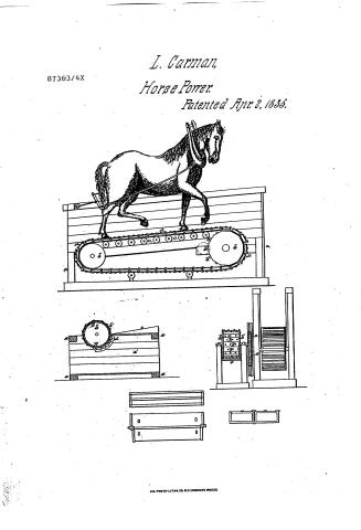 Page 1
-
 Page 2
-
 Page 3
-
 Page 4
-
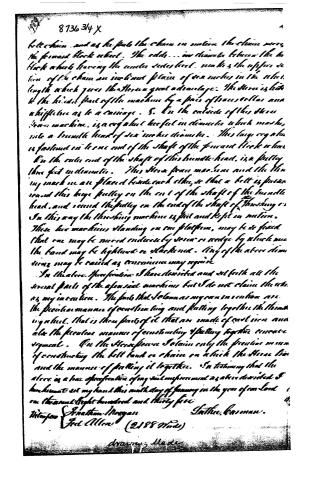 Page 5


U.S. Patent and Trademark Office · Google Patents
Show the transcription Hide (1,472 words)
Machine transcription (LightOnOCR) of the pages as scanned by the USPTO, most of them the handwritten copies made when the records were restored after the 1836 fire. Not checked; it can misread handwriting, so compare it with the scan.
Page 1.
87363/4X
L. Carman,
Horse Power.
Patented Apr. 2, 1855.

A.M. PHOTO-LITH. CO. N.Y. (OSBORNE'S PROCESS)
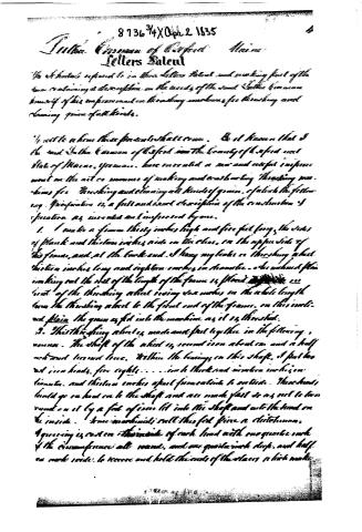
Page 2.
8736 3/4 X Oct. 2 1835
Sutter, Governor of California Maine
Letters Patent
The undersigned request to issue Letters Patent under the following specifications for a threshing machine and the machinery for the same. The undersigned being a citizen of the State of Maine, and having been in the United States for a long time, has been engaged in the business of agriculture and has been a member of the Society of the Arts of the United States for many years. He has been engaged in the business of agriculture and has been a member of the Society of the Arts of the United States for many years. He has been engaged in the business of agriculture and has been a member of the Society of the Arts of the United States for many years.
I will here state the particulars of the invention.
1. I make a frame thirty inches high and five feet long, the sides of plank and thirteen inches wide on the clear, on the upper side of the frame, and at the back end. I hang my beam on the threshing wheel thirteen inches long and eighteen inches in diameter. I have attached a plank making out the rest of the length of the frame 14 inches long and 14 inches wide. The threshing wheel being six inches in the whole length from the threshing wheel to the front end of the frame, on this inclined plain the grain is fed into the machine as it is threshed.
2. The threshing wheel is made and fast together in the following manner. The shaft of the wheel is round iron about one and a half inches and turned true. Within the bearings in this shaft, I put two iron heads, five eighths... inches thick and nineteen inches in diameter, and thirteen inches apart from each other to outside. These heads, being put on and on to the shaft and are made fast so as not to turn round on it by a fork of iron let into the shaft and into the head on the inside. The machine will then feed grain a continuous, and grain is cast on the inside of each head with one quarter inch of the circumference all round, and one quarter inch deep, and half an inch wide, to receive and hold the ends of the stalks which make
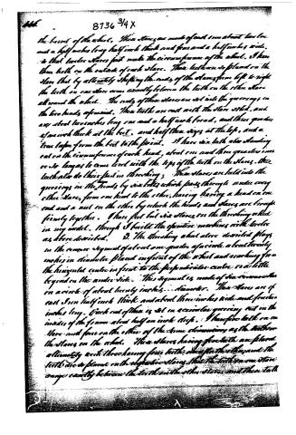
Page 3.
The barrel of the wheel. These stars are made of cast iron about two and a half inches long, half inch thick, and four and a half inches wide. To these twelve stars fasten the circumference of the wheel. I have three teeth on the outside of each star. These teeth are placed on the star that by alternately shifting the ends of the stars from left to right, the teeth on one star come exactly between the teeth on the other stars all round the wheel. The ends of these stars are set into the grooves in the two heads, opposite. These teeth are cast with the star steel, and are about two inches long, one and a half inch broad, and three quarters of an inch thick at the foot, and half their sizes at the top, and a true taper from the foot to the point. I have six teeth also standing out on the circumference of each head, about one and three quarters inches so long as to come level with the tops of the teeth on the stars. These teeth also do their part in threshing; These stars are held into the grooves in the heads by six bolts which pass through under every other star, from one head to the other, having a head on one end and a nut on the other by which the heads and stars are brought firmly together. I have put but six stars on the threshing wheel in my model, though I built the opposite machines with twelve as above described. 3. The threshing wheel above described plays in the course of about one quarter of a circle about twenty inches in diameter placed in front of the wheel and reaching from the horizontal centre in front to the perpendicular centre, or a little beyond on the under side. This segment is made of six iron rods on a circle of about twenty inches diameter. These stars are of cast iron half inch thick and about three inches wide and fourteen inches long. Each end of these is set in a circular groove cut in the inside of the frame about half an inch deep. I have five teeth on one star and four on the other of the same dimensions as the teeth on the stars on the wheel. These stars having flots teeth are placed alternately with those having four teeth one after the other, and the teeth are so placed on the opposite stars that the teeth on one star come exactly between the teeth on the other stars, and their teeth
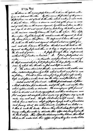
Page 4.
8736 34X
on the stones on the concave surface between the teeth on the cylinder, and then by one can take round the other. They then remove the friction of the yarns, shifted from one set of teeth to the other which makes it more certain to thread them. When in advance an arch made of the yarns on each end of each stone in the concave segment, by which each stone on the concave can be set and moved round, while being the teeth on each in the concave exactly between the teeth on the wheel. There I put three or four lengths across the concave under the segment to hold the stones firm in their places. The segment between the ends of the teeth on the wheel and segment should be about one eighth of an inch, and also between the teeth on the wheel and the teeth on the segment as they pass each other, so large a segment as to admit the knots of grain . . . . . to pass through these segments without being broken or twisted. 4. I put a pulley about six inches . . . . . . . . …
Page 5.
8736 3/4 X
belt chain, and as he pulls the chain in motion the chain moves the forward block wheel. The eddy... in diameter between the two block wheels having the under sides level, makes the upper section of the chain an inclined plane of six inches in the wheel length which gives the Horse a great advantage. The Horse is hitched to the hinder part of the machine by a pair of traces or collars and a hitchline as to a carriage. 5. On the outside of this Horse frame machine, is a cog wheel three feet in diameter which meshes into a tumbler head of six inches diameter. This large cog wheel is fastened on to one end of the shaft of the forward block wheel. On the other end of the shaft of this tumbler head, is a pulley three feet in diameter. The Horse frame machine and the threshing machine are placed beside each other, so that a belt is passed round this large pulley on the end of the shaft of the tumbler head, and round the pulley on the end of the shaft of the threshing machine. In this way the threshing machine is put and kept in motion. These two machines standing on one platform, may be so fixed that one may be moved endwise by seven or eight feet by which means the band may be tightened or slackened. One of the above dimensions may be raised as convenience may require.
In the above specification I have described and set forth all the several parts of the aforesaid machines but I do not claim the same as my invention. The parts that I claim as my own invention are the peculiar manner of constructing and putting together the threshing wheel, that is those parts of it that are made of cast iron and also the peculiar manner of constructing & putting together the carriage segment. On the Horse frame I claim only the peculiar manner of constructing the belt band or chain on which the Horse is hitched and the manner of putting it together. In testimony that the above is a true specification of my said improvement as above described I hereunto set my hand this ninth day of January in the year of our Lord one thousand eight hundred and thirty five.
Witnesses:
Jonathan Morgan
Fred Allen (2188 Words)
Sather Garman.
drawing made
About this record
- Date
- USPTO records
- Listed in
- USPTO records
- This patent does not appear in the Name and Date index.