

Drawings and documents
USPTO scan
The patent as scanned by the USPTO
-
 Page 1
-
 Page 2
-
 Page 3
-
 Page 4
-
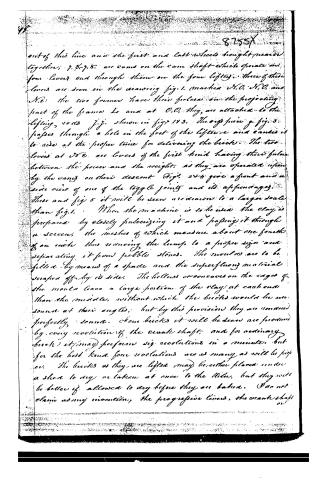 Page 5
-
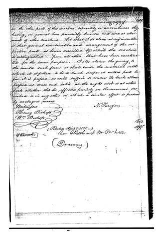 Page 6


U.S. Patent and Trademark Office · Google Patents
Show the transcription Hide (1,637 words)
Machine transcription (LightOnOCR) of the pages as scanned by the USPTO, most of them the handwritten copies made when the records were restored after the 1836 fire. Not checked; it can misread handwriting, so compare it with the scan.
Page 1.
No Printed Specification Available
8755X
H. Sanger
Brick Machine.
Patented Apr. 8, 1835.
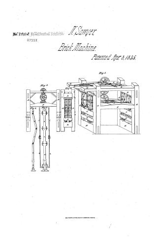
Fig. 1.
Fig. 2.
Fig. 3.
Fig. 4.
Fig. 5.
AM. PHOTO-LITHO. CO. N.Y. (OSBORNE'S PROCESS)
Page 2.
Nathan Sawyer 8755X
Letting Patent
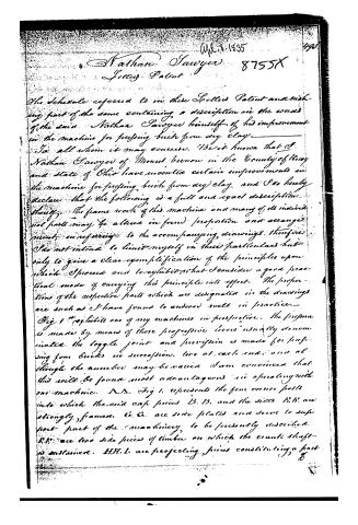
The Schedule referred to in these Specified Patent and making part of the same containing a description in the words of the said Nathan Sawyer himself of his improvement in the machine for pressing brick from any clay.
To all whom it may concern. Be it known that I Nathan Sawyer of Mount Vernon in the County of Knox and State of Ohio have invented certain improvements in the machine for pressing brick from any clay and I do hereby declare that the following is a full and exact description thereof. The frame work of this machine and many of its individual parts may be altered in form proportion and arrangement, in referring to the accompanying drawings therefore I do not intend to limit myself in these particulars but only to give a clear exemplification of the principles upon which I proceed and to exhibit what I consider a good practical mode of carrying this principle into effect. The proportions of the respective parts which are designated in the drawings are such as I have found to answer well in practice.
Fig 1 represents one of my machines in perspective. The pressure is made by means of those progressive levers usually denominated the toggle joint and provision is made for pressing from bricks in succession, two at each end; and although the number may be varied I am convinced that this will be found most advantageous in operating with one machine. A A. Fig 1. represents the four corner posts into which the end cap pieces B. B. and the sides C. C. are strongly framed. C. C. are side plates and serve to support part of the machinery to be presently described. E. E. are two side pieces of timber on which the counter shaft is sustained. H. H. I. are projecting pieces constituting a part of
Page 3.
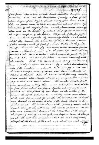
of the frame) upon which certain levers described hereafter are sustained. a, a, are the head-pieces, forming a part of the upper hinge of the toggle joints or progressive levers b, b, c, c. d, d, are piston rods which are worked up and down by the motion of the toggle joints, on the lower ends e, e, of these rods are the pistons by which the pressure is made on the upper surface of the bricks. The joints of the progressive levers are kept together by connecting links 3, 3, 3, 3, which, whilst they prevent the separation of their bearings, admit of their moving with perfect freedom. C, C, are the guide clamps which in this fig. are represented as made of wood framed or otherwise secured into the posts A, A. Within these are contained the boxes or sockets, which serve to guide the piston rods d, d, and cause the piston to enter correctly into the moulds. It is better, however, to make these guide clamps of iron, and they are represented at C, C, fig. 2, which is a direct end view of the machine on a smaller scale than fig. 1. D, D, are the mould clamps, made of wood and boxes or otherwise attached to the posts A, A. The moulds to be presently described stand within these clamps, which are so operated or formed as to receive and retain them. The moulds I make of cast iron sometimes casting them in one entire piece and at other in four pieces which are joined together at each angle and retained in their places by iron hoops on the outside of the mould. The depth of the mould is usually about seven inches at the ends but one inch less at the shallowest part; its length and breadth on the inside is that of the bricks that is to be formed in it. The inside is lined with plates of steel, which I insert through the cast iron. The mould is oval on its outside, and is somewhat larger at the bottom than at the top for the purpose of driving, on wrought iron hoops or bands, to strengthen it. The cast iron measures about two and a half inches through at the swell of the oval, and about one inch at each angle.
Page 4.
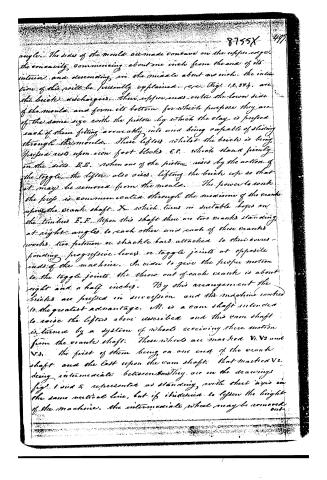
angle. The sides of the mould are made concave on the upper edge, the concavity commencing about one inch from the end of its interior, and descending in the mould about an inch. The insertion of this will be presently explained. (see Fig. 12, 34), are the brick dischargers. Their upper ends enter the lower side of the mould, and form its bottom, for which purpose they are of the same size with the piston by which the clay is pressed, each of them fitting accurately into and being capable of sliding through the mould. These lifters, whilst the bricks is being pressed rest upon iron foot blocks F.F., which stand firmly on the sill B.B. When one of the pistons rises by the action of the toggles, the lifters also rises, lifting the bricks up so that it may be removed from the mould. The power to work the press is communicated through the medium of the crank upon the crank shaft X, which turns in suitable boxes on the timbers F.F. Upon this shaft there are two cranks standing at right angles to each other and each of these cranks works two pistons or shackle bars attached to their corresponding progressive levers or toggle joints at opposite ends of the machine. In order to give the proper motion to the toggle joints the throw out of each crank is about eight and a half inches. By this arrangement the bricks are pressed in succession and the machine worked to the greatest advantage. M. is a cam shaft intended to raise the lifters above described and this cam shaft is turned by a system of wheels receiving their motion from the crank shaft. These wheels are marked V1, V2 and V3, the first of them being on one end of the crank shaft and the last upon the cam shaft, that marked V2 being intermediate between them. They are in the drawings Fig. 1 and 5 represented as standing with their axis in the same vertical line, but if it is desired to lessen the height of the machine, the intermediate wheel may be removed out.
Page 5.
out of this line and the first and last wheels brought nearer together; 7. 8. 7. 8. are cams on the cam shaft which operate on four levers and through them on the four lifters. Three of these levers are seen in the drawing fig. 1. marked N.O. N.O. and N.2: the two former have their fulcra on the projecting part of the frame L and at O.O. they are attached to the lifting rods j.j. shown in figs 123. The only piece g. fig. 3. passes through a hole in the foot of the lifter and causes it to rise at the proper time for delivering the bricks. The two levers at N.E. are levers of the first kind having their fulcra between the power and the weight, as they are operated upon by the cams on their descent. Figs. 3 and 4 give a front and a side view of one of the toggle joints and its appendages. These and fig 5 it will be seen are drawn to a larger scale than fig. 1. When the machine is to be used the clay is prepared by closely pulverizing it and passing it through a screen, the meshes of which measure about one fourth of an inch thus reducing the lumps to a proper size and separating it from pebble stones. The moulds are to be filled by means of a spade and the superfluous material scraped off by its sides. The hollows or concaves on the edges of the moulds leave a large portion of the clay at each end than the middle, without which the bricks would be unsound at their angles; but by this provision they are rendered perfectly sound. From bricks it will be seen are produced by every revolution of the crank shaft, and for ordinary brick it may perform six revolutions in a minute, but for the best kind four revolutions are as many as will be proper. The bricks as they are lifted may be either placed under a shed to dry or taken at once to the kiln, but they will be better if allowed to dry before they are baked. I do not claim any invention, the progressive levers, the crank shaft or
Page 6.
on the other parts of this machine separately or uncombined, they having in general been previously known and used as elements of other machines. But what I do claim as my invention is that general combination and arrangement of the respective parts as herein described by which this machine is distinguished from all others that have been constructed for the same purpose. I also claim the giving to the mould such form as shall cause the material within which it is filled to be so much deeper in certain parts before it is pressed as will suffice to render the brick when pressed as dense and solid at the angles as it is at other parts whether this be effected precisely in the manner described or in any other in which a similar effect is produced by analogous means.
Witnesses
Henry Bishop
Wm. Bishop
N. Sawyer.
(Patented April 8, 1835.)
1584 words
(Drawing)
Published accounts: journal notice
Notice in the monthly list of patents
Journal of the Franklin Institute, new ser., vol. 15 (1835), p. 435 · View the page
197. Brick pressing machine.-Nathan Sawyer, Knox county, Ohio,
Published accounts: journal notice
Notice in the monthly list of patents, with remarks
Journal of the Franklin Institute, new ser., vol. 16 (1835), p. 316 · View the page
27. For a machine for Pressing Brick from Dry Clay; Nathan Sawyer, Mount Vernon, Knox county, Ohio, April 8.
Remarks. Many machines have been made for the purpose of pressing brick from dry clay, the clay being first pulverized and sifted; the power required to make good brick in this way is immense, and most of the machines have failed from their insufficiency in this particular. In the machine here patented, the pressure is applied by means of a toggle joint, which, we are of opinion, is the best arrangement for the purpose. One of the machines is at work in this city, (Washington,) and upon weighing the bricks made by it, we have found them, when baked, to weigh upon an average nearly eight ounces more than good stock brick of the same size, and from the same yard, made in the usual way. The general arrangement of the press we do not think it necessary to describe, but will give some extracts from the specification, concerning points which can be understood without a drawing. The moulds are made of cast-iron, and lined with steel plates. "The sides of the mould are made concave on the upper edge, the concavity commencing about one inch from the end of its interior, and descending in the middle about an inch; the intention of this will be presently explained." "When the machine is to be used, the clay is prepared by coarsely pulverizing it, and passing it through a screen, the meshes of which measure about one-fourth of an inch, thus reducing the lumps to a proper size, and separating it from pebble stones. The moulds are to be filled by means of a spade, and the superfluous material scraped off by its side. The hollows, or concaves, on the edges of the mould, leave a larger portion of clay at each end than in the middle, without which the bricks would be unsound at their angles, but, by this provision they are rendered perfectly sound. Four bricks are made at every revolution of the crank shaft; and for ordinary brick it may perform six revolutions in a minute, but for the best brick four revolutions are as many as will be proper. The bricks as they are lifted, may be either placed under a shed to dry, or taken at once to the kiln, but they will be better if allowed to dry before they are baked. "I do not claim, as my invention, the progressive levers, the crank shaft, or the other parts of the machine separately and uncombined; they having, in general, been previously known and used as elements of other machines; but what I do claim as my invention is that general combination and arrangement of the respective parts as herein described, by which this machine is distinguished from all others that have been constructed for the same purpose. I also claim the giving to the mould such a form as shall cause the material with which it is filled to be so much deeper in certain parts, before it is pressed, as will suffice to render the brick, when pressed, as dense and solid at the angles as it is at other parts, whether this be effected precisely in the manner described, or in any other by which a similar effect is produced by analagous means."
About this record
- Patentee
- DATAMP
- Date
- the Name and Date index of patents, DATAMP, USPTO records
- Invention
- DATAMP
- Listed in
- the Name and Date index of patents, DATAMP, USPTO records, Jim Shaw's X-patent list, the Journal of the Franklin Institute, Burke's List of Patents (1847)
- Burke's 1847 Patent Office list gives the same patent.