

Drawings and documents
USPTO scan
The patent as scanned by the USPTO
-
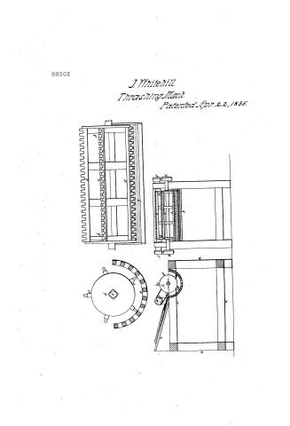 Page 1
-
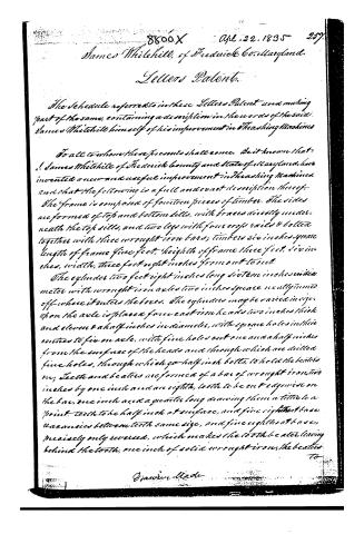 Page 2
-
 Page 3
-
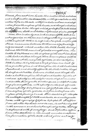 Page 4
-
 Page 5


U.S. Patent and Trademark Office · Google Patents
Show the transcription Hide (1,132 words)
Machine transcription (LightOnOCR) of the pages as scanned by the USPTO, most of them the handwritten copies made when the records were restored after the 1836 fire. Not checked; it can misread handwriting, so compare it with the scan.
Page 1.
8800X
J. Whitehill.
Thrasing Mach.
Patented Apr. 22, 1835.
Page 2.
8800X Apl. 22. 1835 257.
James Whitehill, of Frederick Co. Maryland.
Letters Patent.
The Schedule referred to in these Letters Patent and making part of the same, containing a description in the words of the said James Whitehill himself of his improvement in Threshing Machines.
To all to whom these presents shall come, Be it known that I, James Whitehill of Frederick County and State of Maryland, have invented a new and useful improvement in Threshing Machines, and that the following is a full and exact description thereof.
The frame is composed of fourteen pieces of timber. The sides are formed of top and bottom sills, with braces directly underneath the top sills, and two legs with four cross rails & bolted together with three wrought iron bars; timbers six inches square length of frame five feet, height of frame three feet, six inches, width, three feet eight inches from out to out.
The cylinder two feet eight inches long sixteen inches in diameter with wrought iron axle two inches square neatly turned off where it enters the boxes. The cylinder may be varied in size upon the axle is placed from east iron heads two inches thick and eleven & a half inches in diameter, with square holes in their centres to fix an axle, with five holes cut one and a half inches from the surface of the heads and through which are drilled five holes, through which go half inch bolts, to hold the beaters on; Teeth and beaters are formed of a bar of wrought iron two inches by one inch and an eighth, teeth to be cut edge wise on the bar, one inch and a quarter long drawing them a little to a point. Teeth to be half inch at surface, and five eighths at base, vacancies between teeth same size, and five eighths at base, precisely only reversed, which makes the tooth beater, leaving behind the tooth, one inch of solid wrought iron, the beaters
to
James Whitehill
Page 3.
to be placed on the surface of the cast iron heads, with holes drilled through them to correspond with the formheads at the end of the cylinder, and over the five tooth beaters to be placed a hoop of iron, one inch by three quarters to confine, down at each end, and directly opposite the tooth beaters, through the hoop and beaters holes are drilled & through the holes a bolt or screws confine the hoop and beaters together.
The boxes on which the axles of the cylinder run, made of one piece of cast iron bedded into the frame and at each end, a half inch hole drilled in that, that is placed a metallic box formed of two pieces, running into the cast iron box, dovetailed, over these is placed a piece of wrought iron with holes at each end, through which go bolts down into the frame, and confines boxes and cylinder axles firmly. A pulley to be placed on the axle for the main shaft seven inches in diameter. The feeding roller to be placed on two upright posts, roller to be three inches from the surface of the cylinder, and four inches from the surface of the feeding board. The roller to be four inches square, and two feet eight inches long to be made of wrought iron, with a pulley on the end opposite the main pulley. The cone is formed of twelve square bars, an inch and an eighth square, to fit the cylinder, at each side of the machine is placed two quadruple circles cast iron plates, sixteen inches and a half in diameter, through which pass the wrought iron bars which form the cone well bolted to the sides. The cone is placed from the end of the frame, the top of the machine is covered with a square box and the feeding board is constructed in the usual way.
What I claim as my own invention, and not previously known in the above described Machine, is as follows.
The cylinder two feet eight inches long, sixteen inches in diameter with a wrought iron axle two inches square neatly turned off where it rests on the boxes, upon the axle is placed
Page 4.
blacked, four cast iron heads, two inches thick, and eleven and a half inches in diameter, with square holes in their centres to fix on the axle, with fine holes cut one and a half inches, from the surface of the heads, and through which are drilled fine holes, through which go half inch bolts to hold the beaters on; teeth and beaters are formed of a bar of wrought iron, two inches by one inch and an eighth, teeth to be cut edgewise on the bar one inch a quarter long drawing them a little to a point, teeth to be half inch at surface, and five eighths at base, uniformities between teeth same size precisely, only reversed, which makes the tooth beater, leaving behind the tooth one inch of solid wrought iron, the beater to be placed on the surface of the cast iron heads with holes drilled through them to correspond with the four heads at the end of the cylinder, and over the fine tooth beaters, to be placed a hoop of iron one inch by three quarters of an inch to confine the tooth beaters down at each end, and directly opposite the tooth beaters, through the hoop and beaters, holes are drilled, and through the holes a bolt to confine the hoop and beaters together at each end. A pulley on the axle for main strap seven inches in diameter. Feeding roller six inches space and 2 feet 5 inches long of a wrought iron, with a pulley on the side opposite the main pulley to be placed on upright posts, three inches from surface of the cylinder, and four inches from the surface of the feeding board. This machine operates upon the united principle of tooth and beater, and unites greater power, with requiring less force to propel it. It differs from all other machines now in use, in not having teeth in the concave and has but one feeding roller; that may be dispensed with if necessary; and it further differs from other machines in the small number and peculiar formation of the teeth which gives not only
Page 5.
an increase of power but also threshes grain without use of the feeding roller, if any.
Witnesses
Mrs. J. Ross
George Rice
James Whitehill
Elyon
Published accounts: journal notice
Notice in the monthly list of patents
Journal of the Franklin Institute, new ser., vol. 15 (1835), p. 435 · View the page
247. Thrashing machine.-James Whitehill, Frederick county, Md.
Published accounts: journal notice
Notice in the monthly list of patents (listed with a different spelling or date)
Journal of the Franklin Institute, new ser., vol. 16 (1835), p. 331 · View the page
For a Thrashing Machine; James Whitehall, Frederick county, Maryland, April 24.
About this record
- Patentee
- DATAMP
- Date
- the Name and Date index of patents, DATAMP, USPTO records
- Invention
- DATAMP
- Listed in
- the Name and Date index of patents, DATAMP, USPTO records, Jim Shaw's X-patent list, the Journal of the Franklin Institute, the Journal of the Franklin Institute, Journal, Burke's List of Patents (1847)
- Also listed in a contemporary journal or list under a different spelling or date; the record shown follows the standard lists.
- Burke's 1847 Patent Office list gives the same patent.