

Drawings and documents
USPTO scan
The patent as scanned by the USPTO
-
 Page 1
-
 Page 2
-
 Page 3
-
 Page 4
-
 Page 5
-
 Page 6


U.S. Patent and Trademark Office · Google Patents
Show the transcription Hide (1,927 words)
Machine transcription (LightOnOCR) of the pages as scanned by the USPTO, most of them the handwritten copies made when the records were restored after the 1836 fire. Not checked; it can misread handwriting, so compare it with the scan.
Page 2.
United States Patent
Patent No.: X8837
Washington, H. Pagett
Sales Patent
The schedule referred to in these Letters Patent and making part of the same containing a description on the works of the said Washington H. Pagett himself of his improvement in the Thrashing Machine.
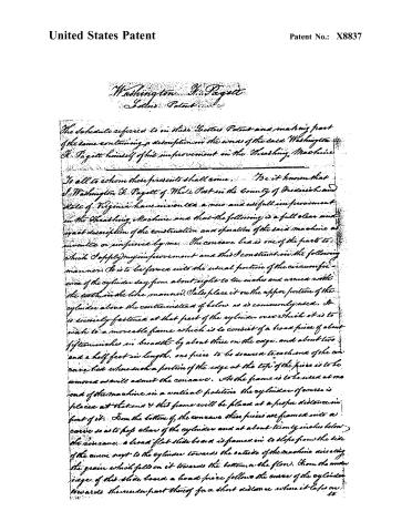
To all to whom these presents shall come, Be it known that I, Washington H. Pagett of White Post in the County of Frederick and State of Virginia have invented a new and useful improvement in the Thrashing Machine and that the following is a full clear and exact description of the construction and operation of the said machine as invented or improved by me. The concave bea is one of the parts to which I apply my improvement and this I construct in the following manner. It is to be formed into the usual portion of the circumference of the cylinder say from about eight to ten inches and armed with the teeth in the like manner. Also place it on the upper portion of the cylinder above the center instead of below as is commonly used. It is securely fastened at that part of the cylinder over which it is to work to a moveable frame which is to consist of a broad piece of about fifteen inches in breadth by about three on the edge, and about two and a half feet in length, one piece to be secured to each end of the concave bea where such a portion of the edge at the top of the piece is to be removed as will admit the concave. As the frame is to be used at one end of the machine in a vertical position the cylinder of course is placed at that end & that frame will be placed at a proper distance in front of it. From the bottom of the concave these pieces are framed into a curve so as to pass clear of the cylinder and at about twenty inches below the concave, a broad flat slide board is framed in to slope from the side of the curve next to the cylinder towards the outside of the machine directing the grain which falls on it towards the bottom or the floor. From the under edge of this slide board a broad piece follows the curve of the cylinder towards the under part thereof for a short distance where it laps on.
Page 3.
United States Patent
Patent No.: X8837
to the top of a long slide board which connects the stairs beneath the cylinder to the other end of the frame of the machine & this board piece protects the springs beneath from dust &c. Below this board piece last mentioned and at the bottom of each end piece of the moveable frame is to be an arrangement to allow of a receding motion of the concave in case of the passage of a stone &c. thus a small friction roller is made to project below the piece somewhere near the centre of from which the end of a spring is to bear & which spring is to be continued horizontally beneath the long slide board from the friction roller towards the other end of the machine frame as may be necessary. The shape of that end of the spring which bears against the friction roller is triangular having one side attached to the spring & the angular edge to be opposed to the roller. thereby forming an inclined plane over which it rides on the front & falls on the back side thus whenever the accidental passage of a stone or other body causes the concave bed to yield from the cylinder. When the roller passes over the angle a pressure is necessary to be applied to the concave bed to send it to its place again. Also apply another mode of effecting the same end of allowing the concave to recede thus. A long arm is secured at the bottom of each end piece to be continued under the long slide board in the same direction as the spring & from one to the other of which at the end furnished from the frame is to extend a broad piece or box for the reception of as much weight as may be found necessary to carry the bed back again to its place after having yielded to the stone &c. & which must be sufficient to keep it to its place during the operation of threshing. This mode may be used instead of the spring, and I think it preferable. Between the first described slide board and the concave a grate is to be used consisting of bent rods placed vertically, but following the general curve of the moveable frame & cylinder for the passage of the grain in front of the men. and in front of this grate an iron shaft is to pass through the end pieces forming the sides of this frame attached to the concave and securely keyed to them. having the ends of said shaft to project sufficiently beyond the said side pieces of this frame to equal the length of the cylinder shaft & to rest upon boxes on which they will revolve (as the concave revolves) placed on the same support
Page 4.
United States Patent
Patent No.: X8837
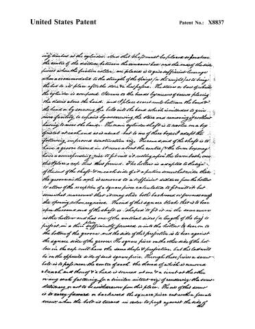
my timbers as the cylinder. And this shaft must be placed so that the centre of the distance between the cone and the one of the side pieces where the friction roller are placed is to give sufficient leverage when a 800 mm rod is to the strength of the spring (or the weight) as to bring the bed to its place after the stone & has passed. The staves or bars of which the cylinder is composed. I secure to the heads by means of screws placing the staves above the band, and I place screw nuts between the band & the head or by screwing the bolts into the band, which is intended to give more facility to repairs by unscrewing the staves and removing it without having to move the band. The main cylinder shaft is to revolve on a box of metal at each end as is usual, but to one of these boxes I adapt the following improved construction viz. The round end of the shaft is to have a groove turned in it near about the centre (or the lower box may have a corresponding rise to fit into it resting upon the lower box, over this I place a cap thus formed. The hollow is adapted to the size of the end of the shaft & on each side of it a portion somewhat wider than the groove in the axle is removed to a sufficient distance from the hollow to allow of the reception of a square piece calculated to fit into it but somewhat narrowed that it may slide both backward or forward as the opening is then required. The end of this square block that is to bear upon the round end of the shaft is shaped to fit it in the same curve as the hollow and has one of the vertical sides (or length of the box) to project in a thin plate sufficiently forward or into the hollow to bear on to the bottom of the groove and the side of this projection is to bear against the square side of the groove. The square piece on the other side of the hollow in the cap will have the same shape & projection, but this last will be on the opposite side of said square piece. Through these pieces a screw bolt is to pass near the centre of each, the thread of which is removed at each end thereof & a head is screwed at one & a screw at the other or any such fastening for a similar intent viz. of rendering the screw stationary or not to be withdrawn from this place. The use of this screw is to carry forward or backward the square piece out with a female screw when the bolt is turned in order to press against the side of the
Page 5.
United States Patent
Patent No.: X8837
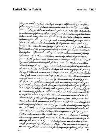
the grooves & thereby keep the shaft steady. The projecting ends of these pieces may be made of harder metals and movable so as to reverse them when necessary. Oil is admitted through a hole at the top. I also propose another mode of operating the spring by means of an extension of the incline plane at the triangular cut by which the front side thereof is carried upwards from the angular edge into a curve forming part of a small circle, the wheel to be described by the friction roller as the lever recedes, so that the roller not passing the point but running up the curve the resistance of the spring would bring it back again after the stone be had passed. Operation. The square shaft with annular cuts forming a pivot on which the movable frame can swing should any stone be driven by the cylinder into the cone, it will yield or recede outwards by means of the revolutions of the friction roller over the front incline, the resistance of the spring against which sends it back again should the stone be small, but should it be large the roller may pass the point of the angle & then the cone will be required to be thrust back to the box, but if the curve is used at the top of the plane the roller does not meet any obstacle but is driven down by the resistance of the spring given the application of the lever & weight the cone equally is brought against the cylinder by the leverage obtained by the length of the frame below the pivot shaft. In using the upper case to any shaft requiring to be occasionally tightened. The heads of the screw bolts are turned which as they have threads only within the portion removed on each side the hollow & passing through the regulating square pieces, these pieces will be driven closer to the square side of the groove on opposite sides thereof which will consequently hold the axle steady again when previously worn by friction. What I claim as my invention and not previously known in the above described machine is First: The arrangements of the spring and friction roller as described at the bottom of the movable frame to allow of the receding motion of the cone, & also the other construction for obtaining the same end by means of the long arms and by a broad piece to apply a weight for the purpose. 2dly: The manner or method of constructing the cap as described for the purpose of adjusting the position of
Page 6.
United States Patent
Patent No.: X8837
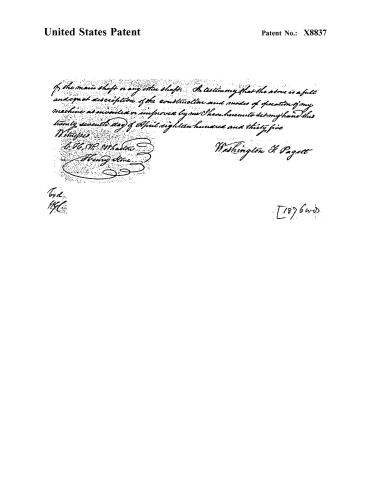
In the main shaft or any other shaft. In testimony that the above is a full and exact description of the construction and modes of operation of my machine as invented or improved by me I have hereunto set my hand this twenty-seventh day of April eighteen hundred and thirty-five.
Witness:
W. H. W. Wharton
Henry Stone
Washington & Pagett
Cert. H.C.
[1896 w.d.]
Published accounts: journal notice
Notice in the monthly list of patents
Journal of the Franklin Institute, new ser., vol. 16 (1835), p. 71 · View the page
281. Thrashing machine.-W. F. Pagett, Whiteport, Frederick co., Va.
Published accounts: journal notice
Notice in the monthly list of patents, with remarks
Journal of the Franklin Institute, new ser., vol. 16 (1835), p. 396 · View the page
31. For a Thrashing Machine; Washington F. Pagett, White Post, Frederick county, Virginia, May 24.
Remarks. A long description is given of this thrashing machine, which we shall cut down by inserting the claim only, which is to "the arrangement of the spring and friction roller to allow of the receding motion of the concave; and also the construction for obtaining the same end by means of the long arms, to apply a weight for the purpose. The manner of constructing the cap for the purpose of adjusting the main, or any other shaft."
Published accounts: journal notice
Notice in the monthly list of patents, with remarks
Journal of the Franklin Institute, new ser., vol. 16 (1835), p. 404 · View the page
51. For a Machine for Making Brick; William Tucker, Luray, Page county, Virginia, May 29.
Remarks. To describe this machine, would be merely to exhibit the particular arrangement adopted by the patentee in placing his hopper, which is to receive the prepared clay, the brick mould, presser, striker, &c., which have frequently been combined together in a very similar manHis claim is, to "the manner in which he combines and puts together the several parts, as set forth." ner.
About this record
- Patentee
- DATAMP
- Date
- the Name and Date index of patents, DATAMP, USPTO records
- Invention
- DATAMP
- Listed in
- the Name and Date index of patents, DATAMP, USPTO records, Jim Shaw's X-patent list, the Journal of the Franklin Institute, Burke's List of Patents (1847)
- The Franklin Institute's journal gives a different date.
- Burke's 1847 Patent Office list gives the same patent.