

Drawings and documents
USPTO scan
The patent as scanned by the USPTO
-
 Page 1
-
 Page 2
-
 Page 3
-
 Page 4
-
 Page 5
-
 Page 6


U.S. Patent and Trademark Office · Google Patents
Show the transcription Hide (1,584 words)
Machine transcription (LightOnOCR) of the pages as scanned by the USPTO, most of them the handwritten copies made when the records were restored after the 1836 fire. Not checked; it can misread handwriting, so compare it with the scan.
Page 2.
United States Patent
Patent No.: X8843
Philo C. Curtis
Letters Patent
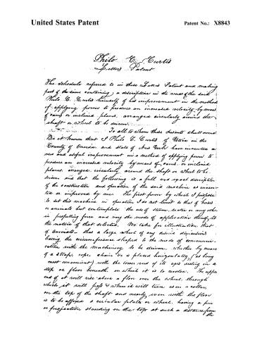
The Schedule referred to in these Letters Patent and making part of the same containing a description in the words of the said Philo C. Curtis himself of his improvement in the method of applying power to produce an increased velocity by means of oams or inclined planes, arranged circularly around the shaft or wheel to be driven.
To all to whom these presents shall come:
Be it known that I Philo C. Curtis of Utica in the County of Oneida and State of New York have invented a new and useful improvement in a method of applying power to produce an increased velocity by means of oams or inclined planes, arranged circularly around the shaft or wheel to be driven, and that the following is a full and exact description of the construction and operation of the said machine as invented or improved by me. The first power by which I propose to set this machine in operation I do not limit to that of horses or animals but contemplate the use of steam, water or any other propelling force and vary the mode of application though to the nature of that selected. We take for illustration that of animals—thus a large wheel of any desired dimensions having the circumference shaped to the mode of communication with the machinery to be driven, whether by means of a strap, rope, chain &c is placed horizontally (as being most convenient) with the lower end of its axis resting in a step or floor beneath, on which it is to revolve. The upper end of it will rise above a floor over the wheel, through which it will pass & where it will turn as in a collar, on the top of the shaft—and nearly even with the floor is to be affixed a circular plate or wheel, having a pin or projection standing on the top at such a distance from the
Page 3.
United States Patent
Patent No.: X8843
the centre of the axis towards the aim of said plate, as will be thought requisite for sufficient length of leverage to form as it were a crank by which when turned round, the wheel and shaft are set in motion, and this effect by the following contrivance. Around this plate or wheel, is raised a circular band or rim of about the width of the radius of the top plate & about the same height as the plate from the floor so as to be smooth or flush with it. This rim is secured to the floor & fits the plate or wheel sufficiently loose to allow it to turn freely. At the distance of say about five & a half times the width of this rim, from the outside thereof is to be secured on the same floor another rim of somewhat greater height than the small one, having the inner edge a plain circle, struck from the centre of the shaft, which will also be the centre of the small rim, and the outer edge serrated or shaped as it were somewhat like the teeth of saw, thereby forming as it were a succession of oams or inclined planes formed at right angles with each other pointing outwards, like saw teeth, the points whereof are rounded & the intersections at the bottom of the teeth likewise for the more easy passage of a friction roller along the raised line thus presented, or upon one side of the tooth & down the other & so alternately. Within these two rims is to be situated another filling up the space between them, but it is to revolve on the same plane & around the smaller one, as a center, it will rise a little higher from the floor than the outside serrated one, having an additional piece or rim fastened to it on the top, of about the same thickness & extending from the outside circumference in the direction of the centre of the shaft to about twice the width of the smaller rim. This piece has a portion of the under side removed at regular intervals, thus by leaving openings between the top of said rim & the top of the revolving one beneath for the passage of levers, or arms extending
Page 4.
United States Patent
Patent No.: X8843
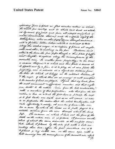
extending from a plate or flat circular collar in which the crank pin revolves, and to which said levers are attached by means of a joint and pin, all except one (which is made immovable thereon) onto the outside edge of the toothed rim, where another paper, below, through said end, and a friction roller below which is intended to roll along the toothed edge, or succession of planes at angles with each other, revolving on the pin. Between said roller & the lever, the pin passes through a thin plate of sufficient length to extend along the circumference of the moveable rim, to another piece projecting as an arm or radius therefrom & to which said thin plate is secured at its opposite end by a pin, so as to play on it as a pivot. This projecting arm is situated at a regular distance from the lever to which it belongs, in the interval between it & the next, of which there are as many as will correspond to the number of levers employed. I find that six levers, form the most convenient & effective number, and that eight-teen teeth to the outside rim, form the best combination, with a machine of this proportion—also that from the situation or line in which the first lever is placed, the next is to fall back one sixth and so on all round, in order to so proportion the motion that the whole combination will work effectively & easily, whatever number of levers, either one, two or more by which the horses are to pull, project to a suitable distance from the rim through which the levers pass. The manner in which I laid out the form of the teeth on the outside rim is as follows. I procured another wheel of about the same diameter as the one first described, which I placed by the side of it with a belt connecting these two—above the first mentioned one is to be placed a very small one, on the same axis, with a belt running over the circumference of the moveable rim which
Page 5.
United States Patent
Patent No.: X8843
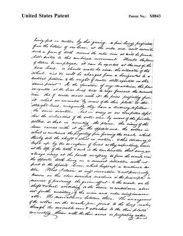
being put in motion by this gearing, a pin being projected from the bottom of one lever, at the outer end, will describe such a form of teeth around the outer rim as will be found, best suited to this combined movement. Should the force of steam be employed, it can be exerted at the end of the horse levers, or should water be used, the situation of the wheel, rims &c will be changed from a horizontal to a vertical position, & the weight of water still exerted on the same point. In the operation of my machine, the power exerted at the horse levers tends to urge forward the movable rim, this of course draws with it the pieces projecting from it, which are connected by means of the thin plate to the straight levers, consequently they have a tendency to follow the same direction, but in doing so are compelled to follow the inclinations of the outer rim, by means of the friction collars, so that in mounting the plane, the rising of the lever carries with it by the opposite end, the collar in which is contained the projecting pin forming the crank, which thereby sets the shaft & wheel in motion, & this tendency is kept up by the succession of levers as they respectively arrive at the top of the teeth & such is the combination that some are always rising at the points necessary to force the crank round the opposite tooth being in a reversed situation with respect to the opposite lever, which keeps up a continuous motion. (What I claim as my invention & not previously known in the above described machine is the principle or manner of producing the given effect to the crank, on the shaft & wheel, according to the device or contrivance above set forth, consisting of the inner and outer rims immovable. The movable one between them. The arrangement of the collar on the crank pin, joined to the lever, moving through the movable rim & attached to the thin plate connecting them with the thin arms or projecting radii.
D. Secund
Page 6.
United States Patent
Patent No.: X8843
secured in said rim, and the manner of adapting the friction roller to produce the desired effect on the outer rim, or inclined planes. In Testimony that the above is a full clear and exact description of the construction & modes of operation of my machine as invented or improved by me, I have hereunto set my hand this seventh day of May in the year eighteen hundred and thirty-five.
Witnesses
Henry Stone
W. R. Morsell
Philo C. Curtis
(Letter written June 9, 1842.)
1507 w D?
Ford.
H.H.
Published accounts: journal notice
Notice in the monthly list of patents
Journal of the Franklin Institute, new ser., vol. 16 (1835), p. 406 · View the page
This stove is the same in form and substance with the cooking stove patented by A. D. Spoor, and described at p. 103. The only difference consists in making the holes in the top plate, to receive kettles, &c., nearer to the edge, and placing a dividing, or intermediate, plate in the drum, with openings in it to direct the heated air under the cooking utensils. The claim made is to the "placing said plate in the cylinder, or drum, as above described, dividing it into two parts, and collecting the heat above such plate, and directing it into a flue opening near the centre." 60. For a Power Gaining Machine; Philo C. Curtis, Utica, Oneida county, New York, May 29.
About this record
- Patentee
- DATAMP
- Date
- the Name and Date index of patents, DATAMP, USPTO records
- Invention
- DATAMP
- Listed in
- the Name and Date index of patents, DATAMP, USPTO records, Jim Shaw's X-patent list, the Journal of the Franklin Institute, Burke's List of Patents (1847)
- Burke's 1847 Patent Office list gives the same patent.