

Drawings and documents
USPTO scan
The patent as scanned by the USPTO
-
 Page 1
-
 Page 2
-
 Page 3
-
 Page 4
-
 Page 5
-
 Page 6
-
 Page 7


U.S. Patent and Trademark Office · Google Patents
Show the transcription Hide (1,568 words)
Machine transcription (LightOnOCR) of the pages as scanned by the USPTO, most of them the handwritten copies made when the records were restored after the 1836 fire. Not checked; it can misread handwriting, so compare it with the scan.
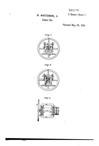
Page 1.
6857X
W. WHITTEMORE, Jr. 2 Sheets—Sheet 1.
Cotton Gin.
Patented May 29, 1835.
Fig. 1.
Fig. 2.
Fig. 3.
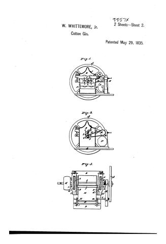
Page 2.
8857X
W. WHITTEMORE, Jr. 2 Sheets—Sheet 2.
Cotton Gin.
Patented May 29, 1835.
Fig. 1.
Fig. 2.
Fig. 3.
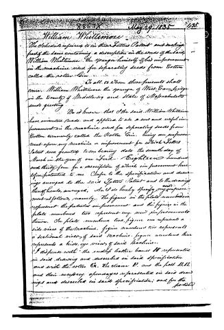
Page 3.
William Whittemore
The Schedule referred to in their Letters Patent and making part of the same containing a description in the words of the said William Whittemore the younger himself of his improvement in the machine used for separating seeds from Cotton called the roller Gin.
To all to whom these presents shall come, William Whittemore the younger of West Cambridge in the County of Middlesex and State of Massachusetts sends greeting.
Be it known that I the said William Whittemore have invented, made and applied to use a new and useful improvement in the machine used for separating seeds from Cotton commonly called the Roller Gin, being an improvement upon my machine or improvement for which Letters Patent were granted to me bearing date the seventh day of March in the year of our Lord Eighteen hundred and thirty-four for a description of which improvement hereafter patented to me. Refer to the specification and drawings annexed to the said Letters Patent and to the drawings thereof here annexed, and I do hereby specify my improvement as follows, namely: The figures in the plate numbered one represent the patented improvement and the figures in the plate numbered two represent my new improvements thereon. On plate numbered two, figure one represents a side view of the machine, figure numbered two represents a sectional view of said machine, figure numbered three represents a bird’s eye view of said machine.
I disjunct with the endless lattice bands H represented in said drawing and described in said specification and with the roller G, the cleaner D, and the post B, b, and their necessary appendages represented in said drawings and described in said specification; and for the
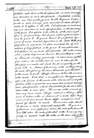
Page 4.
polished cast steel roller b, represented in said drawing and described in said specification. I substitute a wooden roller, and I use another guard Z, like the guard I represented in said drawing, and described in said specification to be applied to the roller (a) represented in said drawing and described in said specification in the same way as the guard I is applied to the roller b, at the same angle from a perpendicular, but upwards instead of downwards as is the guard I. The guards Z and I are fastened by means of screws to small projections on the posts B.B. which projections are represented in plate number two by a & b, instead of being fastened as the guard I was represented to be fastened in my said specification. This roller is about eleven inches long and at the end three fourths of an inch in Diameter swelling gradually to about seven eighths of an inch in the middle part in order to allow for the springing and make all parts bear more equally on the under roller a. Instead of the wooden roller swelling it may be made throughout of the same Diameter and the steel roller made to swell. I prefer, however, to have the wooden roller swell. Cast steel or wrought iron bearings are shown upon and joined to the wooden roller towards each end of the friction rollers as represented and described in said drawing and specification, which I substitute for the said cast steel roller to move upon. This wooden roller is made of some very hard wood, I prefer walnut or hickory. If the wood is boiled either in linseed oil or water before being used, it becomes much harder, stiffer and firmer and much less liable to crack. This wooden roller should be turned or made as smooth as possible. The guard is of sheet iron and passes from below the centre of the frame, B to a little above the centre of the steel roller a, coming very nearly in contact with the roller in the same way as the guard
Page 5.
guard I. is situated with respect to the roller b., respecting that the guard I. is applied downwards and the guard II. upwards. The advantages of using such wooden rollers as I have described, over a metallic roller, instead of two metallic rollers or two wooden rollers, are that the hand and its appendages used with the metallic rollers may be dispensed with, and the metallic lower roller being manufactured or made rough will attain the roughness sufficiently for drawing through the cotton longer than a wooden roller, and such metallic roller cannot well be used with an upper roller of metal without the use of a leather band or some other thing between them. And the wooden roller is much more easily made and less expensive than a roller of steel, but not so durable, and one steel roller will operate not in comparison with a wooden roller as well or better than two wooden rollers. In my improved machine (also see what I call preventers represented in plate numbered two figure by the dotted line) they are placed on the inside of each of the posts B B, these preventers are each composed of two pieces of thin sheet iron or other suitable material, one of these pieces is placed on the posts B B, at the back side of the machine and between the guards, and the posts B B, and is so constructed as to fit closely or very nearly so upon the rollers a (and b), the other part is made to lap over the first part at the top, and is then fastened with the other piece to the post B B, by the screw b, which serves as a hinge or swivel upon which both parts open and shut. This part is so constructed as to shut down very closely or nearly so like the other part upon the rollers a and b on the front side of the machine and when thus down presenting with the other part nearly an uniform surface. These two parts are constructed in the same manner (and are precisely similar. The
Page 6.
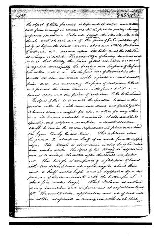
The object of these features is to prevent the cotton and other seeds from coming in contact with the friction rollers. In my improved machine I also use screws m, m, m, m, m, with thumb nuts at each end of the pieces of C.C. instead of using as before the screws m, m, at one end while the pieces of cast iron C.C. moved upon the bolt S, at the other end as a hinge or swivel. The advantage of having screws at each end is that thereby the pieces of cast iron C.C. are made to regulate more equally the bearing and pressure of the friction rollers c.d., c.d., c.d.. On the front side of this machine the screws m, m, are made with a joint c.c. and small pieces a, a, are cut out of the pieces of cast iron C.C. so as to permit the screws m, m, on the front to be bent or turned down and the pieces of cast iron C.C. to be removed.
The object of this is to enable the operator to remove the wooden roller b, with more ease, speed and facility when it becomes worn or unfit for use, or when for any other cause it becomes desirable to remove it. I also use while operating my improved machine, a small wooden trough to receive the cotton represented in plate numbered two figure two by the red lines. This is placed upon the guard D about one half of an inch from the upper edge. This trough is about seven inches long (and about seven inches wide). The object of this trough so applied and placed is to receive the cotton after the seeds are pushed out. This trough is composed of a flat piece of board with two sides placed at right angles about three and a half inches high and is supported by a support e, of the same width with the bottom piece (and about four inches long). What I claim as new and as my invention and improvement is as follows:
1. The construction, application and use of such wooden roller as aforesaid in connection with such steel or
Page 7.
474
8857X 477
roller
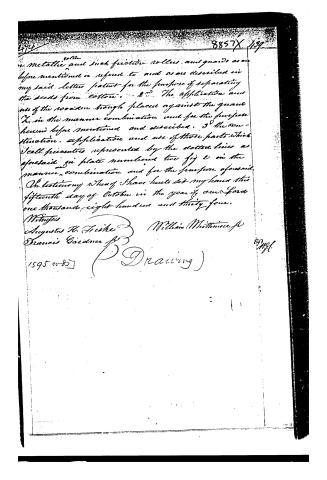
metallic and such friction rollers and guards as are before mentioned or referred to and as are described in my said letter patent for the purpose of separating the seeds from cotton. 2d The application and use of the wooden trough placed against the guard X in the manner combination and for the purpose herein before mentioned and described. 3d The construction, application and use of those parts which I call presenters represented by the dotted lines as aforesaid in plate numbered two fig 2 in the manner combination and for the purpose aforesaid.
In testimony whereof I have hereunto set my hand this fifteenth day of October in the year of our Lord one thousand eight hundred and thirty-four.
Witnesses
Augustus H. Fiske
William Whitmore Jr
Francis Gardner Jr
1595 11-87
(Drawing)
83 Mgl.
Published accounts: journal notice
Notice in the monthly list of patents, with remarks
Journal of the Franklin Institute, new ser., vol. 16 (1835), p. 402 · View the page
44. For an improvement on the Roller Gin, patented March 7th, 1834; William Whittemore, Jr., West Cambridge, Middlesex county, Massachusetts, May 29.
Remarks. This machine is well described, and distinctly represented in the drawing; without the latter, its description could not be made clear, nor would the claim be intelligible. As it is an instrument in which but few of our readers are interested, the necessity of passing it over with this slight notice is the less to be regretted.
About this record
- Patentee
- DATAMP
- Date
- the Name and Date index of patents, DATAMP, USPTO records
- Invention
- DATAMP
- Listed in
- the Name and Date index of patents, DATAMP, USPTO records, Jim Shaw's X-patent list, the Journal of the Franklin Institute, Burke's List of Patents (1847)
- Burke's 1847 Patent Office list gives the same patent.