

Drawings and documents
USPTO scan
The patent as scanned by the USPTO
-
 Page 1
-
 Page 2
-
 Page 3
-
 Page 4
-
 Page 5
-
 Page 6
-
 Page 7
-
 Page 8
-
 Page 9


U.S. Patent and Trademark Office · Google Patents
Show the transcription Hide (2,854 words)
Machine transcription (LightOnOCR) of the pages as scanned by the USPTO, most of them the handwritten copies made when the records were restored after the 1836 fire. Not checked; it can misread handwriting, so compare it with the scan.
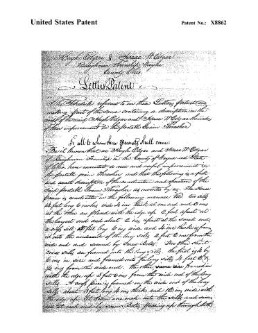
Page 2.
United States Patent
Patent No.: X8862
Hugh Edgar & Isaac M. Edgar
Baughman Township, Wayne County Ohio
Letters Patent
The Schedule referred to in these Letters Patent and making part of the same containing a description in the words of the said Hugh Edgar and Isaac M. Edgar themselves of their improvement in the Portable Grain Thrasher
To all to whom these presents shall come:
Be it known that we Hugh Edgar and Isaac M. Edgar of Baughman Township in the County of Wayne and State of Ohio have invented a new and useful improvement in the Portable Grain Thrasher and that the following is a full and exact description of the construction and operation of the said Portable Grain Thrasher as invented by us. The House Power is constructed in the following manner: Two sills 14 feet long 6 inches wide 4 ins thick at one end and 3 ins at the other are placed with the edge up 2 feet apart at the largest end and about 2 ins apart at the small end, a cross sill 14 feet long 6 ins wide and 4 ins thick is framed into the underside of the long sills 2 feet 2 ins from the wide end and secured by iron Bolts. Two other short cross sills are framed into the long sills. The first is 4 by 6 ins in size and framed into the long sills 4 feet 3 1/2 ins from the wide end. The other same size framed in with the edge up 5 feet 6 ins from the wide end of the long sills. A cross piece is framed on the wide end of the long sills about 3 feet long 4 ins thick and 10 ins wide with the edge up let down one inch into the sills and secured at each end by iron Bolts passing up through both
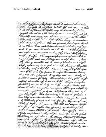
Page 3.
United States Patent
Patent No.: X8862
another crop piece of sufficient length to extend to the outside of the long sill 3 ins thick at the top and as much thick as at the bottom as the builder may think necessary to brace against the action of the Horses. Same width framed into the Sills and secured in the same manner as the other.
Two caps are framed on the top of these pieces, one on each side of the center lengthwise. They are about 6 feet 8 ins in length 3 ins thick 8 ins wide above the center of the long crop sill and 6 ins wide at each end let down into the crop pieces one inch and secured at each end by screw bolts passing up through both. The main shaft is made of wood about 21 ins in length and one foot square a step ledge or of suitable size is inserted into the center of the lower end of the shaft which runs in a cast iron step placed in the center of the long crop sill (before described) one foot of the lower end of the shaft is square to receive the master Wheel. Then a neck or journal 3 ins long and nine inches diameter to receive the caps. The remaining 6 ins of the shaft extends above the caps to receive the lower Wheel. A circular aperture is cut in the caps one half in each 9 inches in diameter which receives the journal on the main shaft made permanent by a screw bolt passing through the cap near the shaft. The shaft stands in a vertical position. The lower wheel is made circular about 2 feet 9 ins in diam. made of 2 thicknesses of 18 1/2 or 2 inch plank. The grain of one thickness crossing the grain of the other and secured together with pins. A notch 10 ins square is made through the centre to receive the top of the shaft. Large wrought iron staples are placed in this wheel to receive the levers to which the Horses are attached. The Horses attached to the levers from 9 to 10 feet from the centre of the main shaft. The master wheel is made of 2 thicknesses of 18 1/2 inch plank and a rim 2 1/2 inches thick. The rim is 3 feet 10 inches diam.
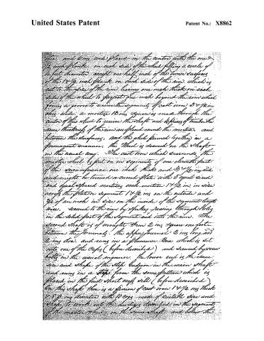
Page 4.
United States Patent
Patent No.: X8862
The, and 6 ins wide) placed in the centre with the one 1/2 inch of plank, on each side of the wheel filling a circle of 4 feet diameter, except one half inch of the inner surface of the 18 1/2 inch plank on each side of the rim, which is cut to the side of the rim leaving one inch thick on each side of the wheel to project one inch beyond the rim which forms a groove to receive the segments of cast iron 3 1/2 in. thick wide, a mortice 13 ins square is made through the center of the wheel to receive the shaft and pieces of timber the same thickness of the rim are placed around the mortice, and between the surfaces, and the whole formed together in a permanent manner. The wheel is secured on the shaft in the usual way. The cast iron which surrounds the mortice wheel is put on in segments of one eleventh part of the circumference one inch thick and 3 1/2 in. wide and might be termed a curved plate with 5 equal sized and equal spaced mortices each mortice 14 1/2 in. in side across the plate or segment 18 1/2 ins on the outside and 3/4 of an inch in side on the inside of the segment length wise. Secured to the rim by spikes passing through holes in the solid part of the segment and into the rim. The second shaft is of wrought iron 2 ins square one foot between the journals. The upper journal 2 ins long and 2 ins dia. and runs in a plummer box which is set into one of the caps (before described) and secured by power bolts in the usual manner. The lower end is the same size and shape of the step cushion in the main shaft and runs in a step from the same pattern which is placed in the first short cap still (before described). On this shaft there is a pinion of cast iron 18 1/2 ins thick 8 1/2 ins diameter with 10 cogs made of suitable size and shape to work into the mortices described in the segment of the master wheel on the same shaft and below the
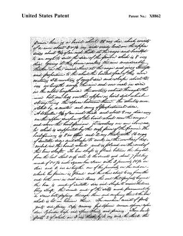
Page 5.
United States Patent
Patent No.: X8862
pinion there is a bevel wheel 28 ins dia. which consists of a rim about 3 1/2 ins wide made level on the upper sides about 3/4 of an inch thick at the verge and bevelled to an angle to suit the size of the pinion which is 8 ins dia. Giving it this form makes the rim considerably thicker in the inside than at the verge and gives strength and proportion to the wheel. The bevelled face of this rim contains 56 mortices of equal size and shape about 2 ins in length across the rim and one inch in size in the centre lengthwise. The mortices extend through the rim but are less on the upper or bevel side which strengthens the space between them. The wheel is completed by a center and arms of proportional size.
A traveller 3/4 of an inch thick and about 8 ins dia. runs on the upper surface of the bevel wheel near the verge and above the bevel pinion. It revolves on an iron axle which is supported by the end piece of the frame. The bevel pinion is 8 ins dia. and 2 ins thick with 16 cogs of suitable size and shape to work in the mortices described in the bevel wheel and is placed on the end of the line shaft. The line shaft is placed between the long side from the last short end sill to the small end and about 7 feet long made of 14 1/2 inch square bar iron with 2 journals 10 1/2 ins dia. and 2 ins in length. One of the journals on the end on which the pinion is placed and the other about 6 ins from the end both run in cast iron boxes. The end that projects beyond the box is made of suitable size and shape to receive the turning shaft. The small end of the side is made permanent by a screw bolt passing through them and confining them to the box which is let in between them. The machine consists of foots, girts, side pieces, caps, concave, fed lefmon, concave lefmon, cylinder, cylinder caps and spinn wheels and pinions. There are 4 foots 2 of which are 3 ins thick by 4 ins wide the other 2 the
Page 6.
United States Patent
Patent No.: X8862
same thickness. 15 ins of the lower ends of them 10 ins wide and the upper ends 8 ins wide. The sides of the posts & lead to the back and front of the frame. There are 2 bottom side girts 2 feet 6 ins long between the posts, framed into them 8 ins from the bottom, one of them 2 by 6 ins in size is framed to the inside of the narrow posts, the other girt same thickness, one half of it same width and the other half 10 ins wide framed in 2 ins from the inside of the wide posts. The wide end & lead to the front of the frame a side piece of the same dimensions as the last named girt, is framed into the oat edge of the wide posts the same distance from the bottom as the girts let into the posts one inch and secured to them with screw bolts. Two girts in which the concave is placed are framed into the posts one inch above the top of the lower side girt. They are 2 ins thick 3 4 ½ ins wide at the front end and 16 at the back end and framed to the inside of the posts. The mortises which receive the back end made longer than the width of the tenons to receive keys for the purpose of regulating the distance between the cylinder and concave to suit the different condition of the grain. The upper side girts are 3 by 4 ins in size framed to the inside of the posts 18 ½ ins above and parallel with the inclined surface of the concave girts. The upper side piece same size framed one inch into the outside of the wide posts. The surface of the side piece has the same inclination and placed the same height as the upper side girts and secured to the posts with screw bolts. Two roof girts 2 by 3 ins in size are framed into the back of the frame one of them 3 ins from the bottom and the other 14 and one the same size framed into the front of the frame 3 ins from the bottom. Two caps are framed across on the tops of the posts one on the front and the other on the back which completes the frame. The front part of the frame 2 feet 6 ins and the back part 3 feet 2 ins high. The concave is composed of 6 bars of ¾ inch square bar iron and 3 bars of flat iron or wood 2 ins wide. The square bars are placed with upper angles towards the centre of the cylinder. The horizontal angles placed
Page 7.
United States Patent
Patent No.: X8862
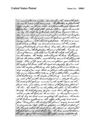
on a circle of 21 4/4 ins. dia. described from the center of the cylinder, die on the inside of the cone gus. The flat bars are placed with upper surface on the same circle and placed alternately between the square bars. The shaft of the cylinder 18 1/2 ins. square bar iron, 35 ins. long. The shaft has 3 journals—each 2 ins. long and 1 1/4 ins. dia. one on each end and one 7 ins. from one end and 2 ins. from the other end. The long end to receive the cylinder and the short end receives a pinion, with which it is provided. The cylinder is made with 3 heads or blocks, one at each end and one in the middle—made of 2 thicknesses of inch. Boards 18 ins. dia. pinned together with the grain of one thickness crossing the grain of the other. A center is made of cast iron of suitable size to fit the shaft with flanges on the outside. The centers extend through the heads. The flanges are let into the outside of them, and the heads secured to the flanges with rivets. 8 bars of 7/8 square bar iron are placed equi-distant round the surface of the heads, with the angle cut projecting 3/8 of an inch above the surface of the heads, and 8 pieces of band iron 2 1/4 ins. wide and 3/4 of an inch thick are placed alternately between them. They are so shaped that 1 1/4 ins. of the widths of them are placed with the flat side on the surface of the heads, and the remaining inch of the widths turned to project in a straight line from the center of the cylinder and cut in the teeth square at the point wide and strong at the bottom of the projecting part of the bar. The teeth in one bar follow the space in the other alternately. The teeth projecting 3/8 of an inch above the square bars which makes the cylinder 20 ins. dia. a band of iron over all the bars at each end completes the cylinder. The center of the cylinder is placed on the upper side gus and side piece 16 ins. from the back of the frame and is covered with a semicircular cap with an aperture in the front part of it through which the dust from the stove is discharged. The feed apron is about 3 feet long. The lower end of it rests on the upper edge of the cone. The upper end is supported by
Page 8.
United States Patent
Patent No.: X8862
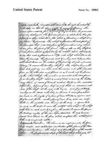
Staples and hooks, connected with screw bolts through the ends of the back caps, so that the upper might be removed at pleasure. The entire upper extends from the front of the frame where the grain and shew are discharged. The cylinder pinion is about 4 ins. dia. and is driven by a spur wheel 20 ins. dia. which is placed on a shaft 3 ins. long between the journals. This shaft is placed on the wide part of the lower side grit and side piece of the same dimension about 13 ins. from the front of the frame. There is also on this shaft a 5 inch pinion which is propelled by the catchet wheel which is also 20 ins. dia. and is placed on a 14½ inch shaft which is 34 ins. between the journals. The journals each 2 ins. long and 14½ ins. dia. with about 4 ins. on the outside of the journals at each end made tapering (to receive the tumbling shaft). This shaft is hung in the lower side grit on one side and the narrow end of the lower side piece, on the other side and placed so as to work into the pinion on the short shaft. The machine is connected to the horse power by a tumbling shaft, which is made of wood or iron as the builder may choose. If made of wood it is about 34½ ins. dia. and about 10 feet long. 2 pieces of iron half an inch thick are riveted on each side of the shaft at the end with bands, and project 34½ ins. beyond the wood with holes in the end to receive pins which are made on the angles of a piece of iron 34½ ins. square and ¾ of an inch thick. Another piece of iron 2 ins. wide, one inch thick in the middle, and thinner at the ends, a square hole is made in the centre to receive the catchet wheel shaft or lower shaft with holes in each end 4 ins. from the centre to receive the pins on the contrary angles of the iron before described. The ends turned round and closed on the pins which complete the catchet joint. Both ends are made alike.
Improvements Claimed — We claim as our improvement, the peculiarly simple and substantial construction of the frame of the threshing machine. The cheap and durable form of the master wheel. The proportionate shape of the bear wheel which gives it
Page 9.
United States Patent
Patent No.: X8862
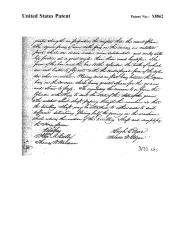
greater strength in proportion his weight than the usual plan. The square pieces of iron with pins on the corners, in ratchet joint, which are easier made, more substantial, and works with less friction at a great angle, than those used heretofore. The form of the bar and the bar tooth cylinder, the teeth of which are not liable to fly out with the centrifugal force of the cylinder when in motion. Placing wood or flat bars between the square bars in the concave which leaves greater space for the grain and straw to pass. The regulating the concave to or from the cylinder with keys to suit the state of the state of the grain. The ratchet wheel shaft passing through the machine so that the tumbling shaft may be attached to either end to suit different situations placing half the gearing in the machine which reduces the motion of the tumbling shaft and simplifies the Horse power.
Witnesses
Alex M. Bulley
Thomas M. Waldron
Hugh Edgar
Isaac M. Edgar
3/33 287
Published accounts: journal notice
Notice in the monthly list of patents
Journal of the Franklin Institute, new ser., vol. 16 (1835), p. 142 · View the page
319. Thrashing machine.-H. Edgar, and J. W. Edgar, Wayne co., Ohio,
Published accounts: journal notice
Notice in the monthly list of patents, with remarks
Journal of the Franklin Institute, new ser., vol. 17 (1836), p. 41 · View the page
9. For a Thrashing Machine; Hugh and Isaac W. Edgar, Wayne county, Ohio, June 6.
Remarks. This is called a "Portable Grain Thrasher," but a horse power, which is certainly a separate and distinct machine, is also described in the same specification. The thrashing machine works by a cylinder and concave, and the general construction of the horse power is the same with many others. "We claim, as our improvement, the peculiarly simple and substantial construction of the frame of the horse power and machine. The cheap and durable form of the master wheel; the proportionate shape of the bevil wheel, which gives it greater strength in proportion to the weight than the usual plan. The square pieces of iron with pins on the corners in ratchet joint, which are easier made, more substantial, and work with less friction at a great angle than those used heretofore. The form of the bar and bar tooth cylinder, the teeth of which are not liable to fly out by the centrifugal force of the cylinder when in motion. Placing wood or flat bars between the bars in the concave, which leave greater space for the grain. The regulating the concave to or from the cylinder with keys, to suit the state of the grain. The ratchet wheel shaft passing through the machine, so that the tumbling shaft may be attached to either end to suit different situations. Placing half the gearing on the machine, which reduces the motion of the tumbling shaft, and simplifies the horse power." If the patentee can sustain all the foregoing claims, together with an exclusive right to his two machines, he will do more than we believe he can accomplish.
About this record
- Patentee
- DATAMP
- Date
- the Name and Date index of patents, DATAMP, USPTO records
- Invention
- DATAMP
- Listed in
- the Name and Date index of patents, DATAMP, USPTO records, Jim Shaw's X-patent list, the Journal of the Franklin Institute, Burke's List of Patents (1847)
- Burke's 1847 Patent Office list gives the same patent.