

Drawings and documents
National Archives restored drawings: drawing
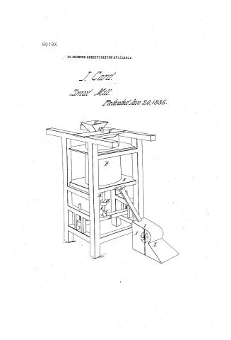
John Card's Patent Drawing for an Elastic Accelerating Smut Mill

National Archives, Restored Patent Drawings (Record Group 241) · Full-size scan at the National Archives · Catalog record
Show the text on the drawing Hide (41 words)
Words on the drawing as machine-read by the National Archives; not checked. Useful mainly for searching.
83. MILLS. / Grain Scourers. / Cylinder, Vertical. / $150 / CATION / x-8600 / 891.8-A / JOHN CARD'S / DIVISION. / Elastic Accelerating Smut Mill. / Patented 20th June 1835 / DrawingA. / We / G.S.Dei / on
USPTO scan
The patent as scanned by the USPTO
-
 Page 1
-
 Page 2
-
 Page 3
-
 Page 4
-
 Page 5
-
 Page 6


U.S. Patent and Trademark Office · Google Patents
Show the transcription Hide (1,784 words)
Machine transcription (LightOnOCR) of the pages as scanned by the USPTO, most of them the handwritten copies made when the records were restored after the 1836 fire. Not checked; it can misread handwriting, so compare it with the scan.
Page 1.
8918X
NO PRINTED SPECIFICATION AVAILABLE
J. Card.
Smut Mill.
Patented Jan. 20, 1835.

Page 2.
June 20, 1895
John Card, of Gainesville, State of New York, —
Letters Patent.
The schedule referred to in these Letters Patent, and making part of the same, containing a description in the words of the said John Card himself of his improvement in the Smut Mill called the Elastic accelerating Smut Mill —
To all to whom these presents shall come,
Be it known, that I John Card of the town of Gainesville in the County of Genesee, and State of New York, have invented a new and useful improvement in the Smut Mill called the Elastic Accelerating Smut-Mill, and that the following is a full and exact description thereof.
1. This mill consists of a cylinder through which a shaft passes, and to which shaft the cylinder is hung or attached, and upon which it revolves, the shaft being perpendicular which shaft is represented in drawing A, accompanying this specification by the letter A, the cylinder is designed to be two feet and four inches in length and eighteen inches in diameter at the bottom and fifteen inches in diameter at the top, or such other length or size as may best suit the builder, each end of the cylinder is covered with sheet iron, thickly perforated, the rough side placed out.
The surface of the cylinder is designed to be covered with a card or cards, formed by placing small nails about half an inch in length into or driving them through firm and substantial leathers or thin and firm sole leather, or any other suitable elastic substance. The nails are to be placed or driven through the leather or other substance, at a point one fourth of an inch distant from each other, the nail to be used in the construction of said card or cards, may be represented by the numbers ten twelve, or fourteen of “saddle tacks,” usually so called cut off at the point, so as to remain about half an inch in length, and
Page 3.
all nails manufactured expressly for making said cards, should correspond in size and proportion thereto. The cards are designed to be made about three inches wide, and placed upon the cylinder by winding the same around the cylinder in the form of a screw, and nailing the same at proper distances and round so as to cover entirely the whole surface of the cylinder. The nails should be driven through or placed in the narrow strips of leather or other substance above mentioned, in regular rows, or nearly so, one fourth in an inch apart, and the nails in each row to be about that distance from each other, which rows should vary about twenty two and a half degrees from a line directly across said strips of leather, or other substance in which said nails are placed, or the said nails may be driven or placed in such other manner or order as to be deemed best calculated to promote the object designed. The said cylinder may also be constructed, and by me has been constructed in the following manner, that is to say, The axis of the cylinder to be constructed & covered in the manner first described and the surface of said cylinder instead of being covered by the card above mentioned to be covered with circular plates or staves adapted to the size of the cylinder which plates or staves are made of cast iron, one fourth of an inch thick, the convex or outside of which plates or staves is covered with points or spurs cast with, & being a part of the said plates or staves, which points or spurs are one fourth of an inch in length, and tapering regularly from the said plates, or staves to a point and to be square their whole lengths, which points or spurs should be set upon the plates, or staves that in the revolution of the cylinder each point or spur shall move cornerwise, or with one corner in front. The points or spurs should also be arranged, that the sides thereof, at the plate or stave, shall be at equal distances apart from each other & which distance should be about, one eighth and one sixteenth part of an inch, said
Page 4.
staves or flats reach from one end of the cylinder to the other and are fastened firmly thereto, with screws, and iron bands, at the top and bottom thereof.
2. The cylinder constructed in either of the ways above described and attached to or hung upon, the perpendicular shaft "A," above mentioned, is designed to revolve within a sheet iron concave, thickly perforated with a small round punch so constructed as to cut out a small piece of the sheet iron in making each hole, such hole to be too small to admit a kernel of wheat to pass through and the hole to be as near each other as the strength of the iron will admit. The hole should be punched from the outside of the concave, so as to leave the inside thereof rough. The concave is represented in drawing "A," by the letter "B" and is designed to be stationary.
The difference between the diameters of the top and bottom of the concave, is designed to correspond with the difference between the diameters of the top and bottom of the cylinder, is designed to correspond with the difference between the diameters of the top and bottom of the cylinder. The cylinder is designed to revolve within the said concave "B" in such manner that the extremities of the nails, points or spurs shall not in the revolutions of the cylinder approach nearer than one quarter of an inch to the inside surface of the sheet iron concave "B" nor pass in the revolutions of said cylinder at a distance greater than half an inch from said inside surface, but to revolve in such intermediate space, as shall be best calculated to accomplish the object of the machine, which distance may be varied at pleasure by raising or lowering the cylinder by means of screws, entering the ends of the bridge tree "D" upon which rests the lower end of the perpendicular shaft "A," which shaft is made of iron or steel, and to be of such size and length, as shall be most desirable, and to stand in an iron or metallic box or oil pot, fastened in the bridge tree.
Page 5.
570.
8918X
"D" which box or oil pot is represented in said drawing A, by the letter "C," the said cylinder is propelled by a strap or band passing from the propelling power around a pulley or wheel attached to said perpendicular shaft, "A," which said pulley or wheel is represented in said drawing A, by the letter "E." It being designed that the said cylinder of the sign above described, when constructed by being covered with the elastic cord first above herein described, shall perform six hundred revolutions, or thereabouts in each minute and when said cylinder is constructed by being covered with the cast iron plates or stay above described, between seven and eight hundred revolutions should be performed in each minute.
3. The perpendicular iron shaft "A" is supported and held at the top by a bridge tree, represented in said drawing A, by the letter "F," or in such other way as the nature of the frame in which the cylinder and concave may be placed shall make it most convenient, the said cylinder and concave may be placed in a common frame represented in drawing A, or fastened firmly to a building or put up in any other convenient manner. The grain which this machine is designed to clean from dust or filth, enters the mill at the hopper "G" (see drawing A) and passes thence into the aperture between the concave "B" and the said cylinder while in motion and is discharged thence through the spout, "I," (as represented in drawing A) into a common sawing mill, or a windmill constructed for the purpose and attached to the frame as represented by the letter "J," in drawing A. "K," represents a space or box below the concave "B," into which the grain falls from the space between the said cylinder, and concave, and from which it passes to the spout "I," and in order to prevent the grain from passing through the floor of said space or box "K" a circular guard or partition formed by two semicircles attached to different parts of the floor, to said box "K" being the two
Page 6.
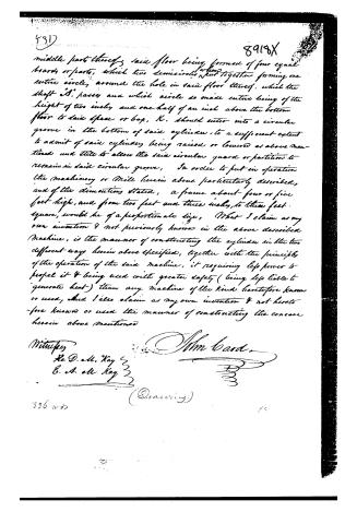
middle parts thereof, said floor being formed of four equal boards or parts, which two semicircles put together forming one entire circle, around the hole in said floor thereof, which the shaft "A" passes and which circle so made entire being of the height of two inches and one half of an inch above the bottom floor to said space or box, K. should enter into a circular groove in the bottom of said cylinder, to a sufficient extent to admit of said cylinder being raised or lowered as above mentioned and still to allow the said circular guard or partition to remain in said circular groove. In order to put in operation the machinery or Mill herein above particularly described, and of the dimensions stated, a frame about four or five feet high, and from two feet and three inches to three feet square, would be of a proportionate size. What I claim as my own invention & not previously known in the above described Machine, is the manner of constructing the cylinder in the two different ways herein above specified, together with the principles of the operation of the said machine, it requiring less power to propel it & being used with greater safety (being less liable to generate heat) than any machine of the kind heretofore known or used, and I also claim as my own invention & not heretofore known or used the manner of constructing the cone herein above mentioned.
Witnesses
Re D. M. Kay
E. A. M. Kay
John Ward
(Drawing)
836 2007
Published accounts: journal notice
Notice in the monthly list of patents
Journal of the Franklin Institute, new ser., vol. 16 (1835), p. 143 · View the page
367. Smut mill.-John Card, Genesee county, N. Y.
Published accounts: journal notice
Notice in the monthly list of patents, with remarks
Journal of the Franklin Institute, new ser., vol. 17 (1836), p. 53 · View the page
57. For a Smut Mill; John Card, Gainsville, Gennesee county, New York, June 20.
Remarks. The patentee denominates this an "Elastic, Accelerating, Smut Mill," and furnishes a description of much length and particularity. A vertical shaft is to carry a cylindrical rubber, which may be two feet four inches high, fifteen inches diameter at top, and eighteen at bottom. This is to be surrounded by a stationary sheet iron case, punched from the outside so as to constitute it a concave rubber. The inner, or revolving, cylinder is also to be converted into a grater by covering the ends with punched sheet-iron, and the sides with strips of leather, into which nails, or tacks, are driven from the inside, so as to form a kind of elastic card. Instead of this, however, it is proposed sometimes to cover the outside with pointed cast-iron staves; the term "elastic" will, in this case, not very aptly apply. "What I claim as my own invention, and not previously known, in the above described machine, is the manner of constructing the cylinder in the two different ways herein above specified, together with the principles of the operation of said machine, it requiring less power to propel it, and being used with greater safety, being less liable to generate heat, than any machine of the kind before known or used. I also claim as my invention, the manner of constructing the concave hereinbefore mentioned." The machine is, substantially, so like a host of others that it would be no easy task to make out a claim which should not be too broad.
About this record
- Patentee
- DATAMP
- Date
- the Name and Date index of patents, DATAMP, USPTO records
- Invention
- DATAMP
- Listed in
- the Name and Date index of patents, DATAMP, USPTO records, Jim Shaw's X-patent list, the Journal of the Franklin Institute, Burke's List of Patents (1847)
- Burke's 1847 Patent Office list gives the same patent.