

Drawings and documents
National Archives restored drawings: drawing
Charles Hill's Patent Drawing for a Rotary Steam Machine

National Archives, Restored Patent Drawings (Record Group 241) · Full-size scan at the National Archives · Catalog record
Show the text on the drawing Hide (36 words)
Words on the drawing as machine-read by the National Archives; not checked. Useful mainly for searching.
121 STEAM ENGINES, / Rotary Impact. / 8932 x / DIVISION. / CHARLES HILL AS / Rotary Steam Engine. / Patented. 26June. 1835. / V.22.14144, / Ge / II / I. / te / Fr
USPTO scan
The patent as scanned by the USPTO
-
 Page 1
-
 Page 2
-
 Page 3
-
 Page 4


U.S. Patent and Trademark Office · Google Patents
Show the transcription Hide (1,134 words)
Machine transcription (LightOnOCR) of the pages as scanned by the USPTO, most of them the handwritten copies made when the records were restored after the 1836 fire. Not checked; it can misread handwriting, so compare it with the scan.
Page 1.
8932X
C. Hill,
Rotary Steam Engine.
Patented June 26, 1835.
NO PRINTED SPECIFICATION AVAILABLE

Page 2.
8932x
Charles H. Pell
Letters Patent
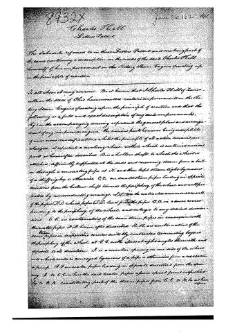
The Schedule referred to in these Letters Patent and making part of the same containing a description in the words of the said Charles H. Pell himself of his improvement in the Rotary Steam Engine operating upon the principle of reaction.
To all whom it may concern: Be it known that I, Charles H. Pell of Xenia, in the state of Ohio have invented certain improvements in the Rotary Steam Engine operating upon the principle of reaction and that the following is a full and exact description of my said improvements.
Fig. 1 on the accompanying drawing represents the general plan and arrangement of my improved engine, the various parts however being susceptible of numerous modifications whilst the principle of its action remains unchanged. A represents a revolving wheel, within which is contained various parts as hereinafter described. B is a hollow shaft, to which the wheel is attached, sufficiently supported at the ends and receiving steam from a boiler through a connecting pipe at N, and there kept steam tight by means of a stuffing box or otherwise. C.C. are small steam pipes leading in opposite directions from the hollow shaft towards the periphery of the wheel and well protected by nonconducting coverings. L.L. are the contracted commencements of the pipes D.D. which pipes D.D. lead from the pipes C.C. in a curve corresponding to the periphery of the wheel, and enlarge to any desired dimensions. E.E. are continuations of the same steam pipes in connexion with the water pipes F.F. hereinafter described. H.H. are continuations of the same steam pipes in serpentine courses suitably contracted terminating beyond the periphery of the wheel, at G.G. with issues at right angles therewith and opposite to its direction. I is a circular opening on one side of the wheel into which water is conveyed by means of a pipe or otherwise from a reservoir or pump. J.J. are water pipes leading in opposite directions from the opening I to C.C. where the said water pipes assume special forms respectively to H.H. constituting parts of the steam pipes from C.C. to H.H. as hereinafter
Page 3.
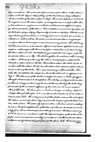
The said water pipes continue from thence to their terminations at H. H., beyond the periphery of the wheel terminating with orifices the same as those of the steam pipes at G. G. The water pipes from C. C. to H. H. may surround the steam pipes encasing the same or pass within them or be continued in any manner which will present a sufficient surface for the condensation of the steam. The water pipes are connected by a pipe N. for the purpose of equalizing the quantity of water in the pipes H. H. the revolving wheels may be enclosed in a casing of wood or metal of a circular or other form within which the water and condensed steam may escape and from thence be conveyed as convenience may direct. The wheel may be likewise used as a condenser by means of water applied to its outer surface, dispensing with the water pipes as described and terminating the steam pipes at C. C. but still using a serpentine conveyance for the condensed steam as in Fig 1. The whole may then be enclosed within a casing as before. Instead of allowing the steam to escape from a fixed boiler through a steam tube at the top I sometimes allow the whole boiler to revolve with the wheel. In this case the steam tube extends out from the centre of one head of the boiler, their axes coinciding with each other. This pipe then constitutes the shaft to which the wheel A. is affixed as in Fig 1. The other end of the boiler is supported upon a hollow gudgeon through which water is to be supplied. The whole quantity of water contained therein at any one time may be small the over heating the boiler being prevented by the constant diffusion of the water over its inner surface.
Mode of Operation. The steam from a boiler entering a revolving shaft at N. passes through the pipes C. C. and the contracted points L. L. to the enlarged pipes D. D. The enlargement of these pipes reduces the velocity of the steam and proportionally increases the surface against which reaction takes place. The extremely rapid motion which would be necessary to ensure the full application of the steam if allowed to escape immediately from the contracted points is thereby avoided. The steam arriving at L. L. comes in contact with the exposed surface of the cold water pipes and is condensed creating a vacuum and the condensed steam is thrown out by its centrifugal force at the orifices G. G. The condensed steam
Page 4.
8432x
1340
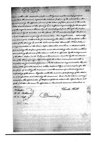
steam within the serpentine pipe will by means of the centrifugal force maintain the vacuum against the external pressure of the atmosphere thereby increasing the effective power of the steam fifteen pounds to the inch. Water is introduced at the opening I, in sufficient quantity for the purposes of the engine and is thrown by its centrifugal force through the serpentine tubes and by its reaction at the issues H, H, compensates for the power which is expended in giving it momentum. Air may be used separately in connexion with water for condensing the steam with suitable alterations of the opening I, and the tubes connected therewith. What I claim as my invention in the herein before described machine is the principle of increasing the surface of reaction and diminishing the motion without diminishing the power of the steam which is effected by the enlargement of the steam pipes (as at D, D,) and the vacuum created by the condensation of the steam giving a high velocity to the wheel accompanied with a corresponding increase of power. I also claim as my invention the introduction of water and air either separately or in connexion for the purpose of creating the vacuum, and the manner of introducing and disposing of the same, together with the manner of disposing of the steam so as to assist in maintaining the vacuum. And I also claim as my invention the application of the principles to attain the object herein set forth whether the same be effected in the precise manner described or otherwise.
W. Douglas
W. C. Polham
A. C. Aff
Charles Hill
(Drawing)
1105 n.07
E.
Chf.
Published accounts: journal notice
Notice in the monthly list of patents
Journal of the Franklin Institute, new ser., vol. 16 (1835), p. 214 · View the page
382. Rotary steam engine. Charles Hill, Zanesville, Ohio,
Published accounts: journal notice
Notice in the monthly list of patents, with remarks
Journal of the Franklin Institute, new ser., vol. 17 (1836), p. 57 · View the page
72. For a Rotary Steam Engine; Charles Hill, Zanesville, Muskingum county, Ohio, June 26.
Remarks. To understand the whole of the references made in the claim would require a drawing, and as our confidence in the Rotary Steam Engine is small, and our objections will yield to the omnipotence of success only, we wait the arrival of such a proof. This is one of the reaction engines, and the claim is to "the principle of increasing the surface of reaction, and diminishing the VOL. XVII-No. 1 JANUARY, 1836. 8 motion, without diminishing the power of the steam; which is effected by the enlargement of the steam pipes, (as at D, D,) and the vacuum created by the condensation of the steam, giving a less velocity to the wheel, accompanied by a corresponding increase of power. I also claim as my invention the introduction of water and air, either separately or in connexion, for the purpose of creating the vacuum, and the manner of introducing and disposing of the same; together with the manner of disposing of the steam so as to assist in maintaining the vacuum. I claim as my invention the application of these principles, to attain the objects herein set forth, whether the same be effected in the precise manner described, or otherwise."
About this record
- Patentee
- DATAMP
- Date
- the Name and Date index of patents, DATAMP, USPTO records
- Invention
- DATAMP
- Listed in
- the Name and Date index of patents, DATAMP, USPTO records, Jim Shaw's X-patent list, the Journal of the Franklin Institute, Burke's List of Patents (1847)
- Burke's 1847 Patent Office list gives the same patent.