

Drawings and documents
National Archives restored drawings: drawing
Amos Miner's Patent Drawing for a Pump

National Archives, Restored Patent Drawings (Record Group 241) · Full-size scan at the National Archives · Catalog record
USPTO scan
The patent as scanned by the USPTO
-
 Page 1
-
 Page 2
-
 Page 3
-
 Page 4
-
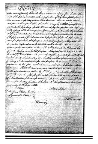 Page 5


U.S. Patent and Trademark Office · Google Patents
Show the transcription Hide (1,764 words)
Machine transcription (LightOnOCR) of the pages as scanned by the USPTO, most of them the handwritten copies made when the records were restored after the 1836 fire. Not checked; it can misread handwriting, so compare it with the scan.
Page 1.
8954X
A Miner.
Pump Brake.
Patented July 7, 1835.
NO PRINTED COPY OF SPECIFICATION IN OFFICE.
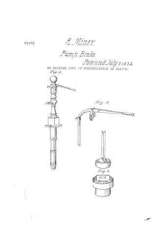
Fig. 1.
Fig. 2.
Fig. 3.
Page 2.
July 7, 1895
Amos Minor, Oldbridge, New York
8954X
Letters Patent
The Subject referred to in the Letters Patent and nothing part of the same containing a description in the words of the said Amos Minor himself of the improvement in Water Pumps.
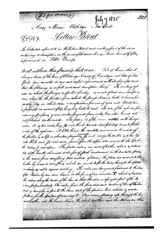
To all whom these presents shall come: He it known that I Amos Minor of the Town of Oldbridge, County of Onondaga and State of New York have invented a new and useful improvement in Water Pumps and that the following is a full and exact description thereof. The working cylinder in which the plungers or pistons operate, is made of cast iron except in cases where the the fountain from which the pump draws is liable to become frequently dry in which case a composition formed of zinc and Black tin is preferable on account of its being less liable to rust. The size of the cylinder for ordinary purposes is nine inches long and four inches diameter turned out and polished on the inside. The piston is of the same metal with the cylinder, it is two inches long 1/4 inch thick turned and polished so as to fit the inside of the cylinder. A little below the middle and around the inside of the piston is a lip or shoulder projecting 1/4 inch over; the center is a bar 3/8 inch thick and 1/4 inch wide faced off on the upper side even with the lip for the valves to rest upon. The piston valves are made of leather which is saturated with "Furth's chemical water proof paint" and covered with metallic plates in the usual form excepting that instead of screws, the plates are secured to the leather by brass or iron rings which are made to fit the holes through the plates so closely as not to require riveting. The valves are hung and fastened to the bar of the piston by an iron lever in the form of an inverted T which is laid on the valves along the center of the bar so that the stem or upright part of the T rises perpendicularly 1/2 inches from the face side and center of the of the bar and is hung by a pin to the lower end of the piston Rod which is made forked for the purpose of receiving it. Iron screws passing up through the bar and leather into the levers secure the whole together and the valves on the
Page 3.
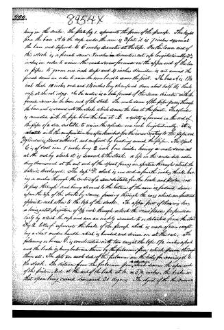
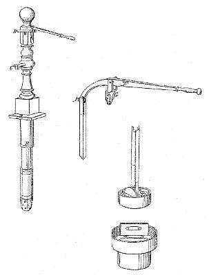
hung in the centre. The plate fig. 1. represents the form of the pump. The height from the base A to the top under the wire is 3 feet; it is 7 inches square at the base and tapered to 6 inches diameter at the top. On the lower end of this stock is a female screw 3 inches in diameter, cut up longitudinally 3 1/4 inches in order to receive the male screw formed on the upper end of the brass pipe, to form one inch deep and 4 inches diameter is cut around the female screw in order to receive the iron band to secure the joint. The base A is 1 1/4 inch thick 10 inches wide and 14 inches long and tapered down about half its thickness at the cut edges. In the centre is a hole formed of the same diameter with the female screw in the lower end of the stock. The male screw of the pipe passes through the base and is screwed into the stock which secures the base at the joint. The cylinder is connected with the pipe below the base at B. a cavity is formed in the end of the pipe of a size suitable to receive the cylinder one inch longitudinally. It is situated with the construction hereafter described for the inner coating to the pipe and the cylinder is placed within it, and confined by banding around the pipe. The spout C is of cast iron 5 inches long 2 inch bore inside, having a male screw cut at the end by which it is screwed to the stock. A lip in the under side extending downward at the cut end of the spout forms an aperture through which the water is discharged. The cup D, which is one and a fourth inches thick, having a median through the centre of a size suitable for the brake and piston rod to pass through and being screwed to the bottom of the wire is fastened down upon the top of the stock by screws passing through the ears which are fastened opposite each other to the top of the stock. The upper part of the wire has a horizontal projection of 3/4 inch through which the screw passes perpendicularly by which the cup and wire are readily secured to or detached from the stock. Fig. 2. letter f represents the brake of the pump which is made of iron excepting a short wooden handle which is bandied and driven on at the end. The fulcrum or beam G is constructed with two ears at the top 1 1/2 inches apart and the brake is hung between them by the fulcrum pin which passes through them all. The dots on each side of the fulcrum are the holes for securing it to the stock. The distance from the fulcrum pin to the upper end of the piston rod at the end of the brake at H is 5 3/4 inches, the brake in that space being curved downward 20 degrees. The object of this curvature
Page 4.
89544X
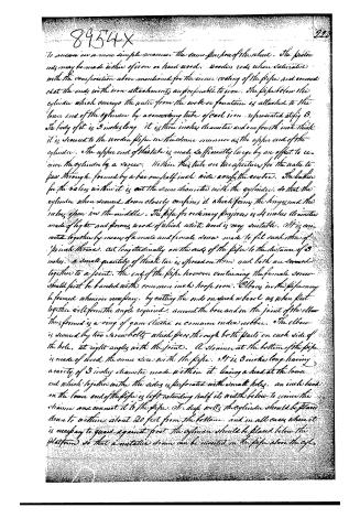
To answer in a more simple manner the same purpose of the wheel. The piston rods may be made either of iron or hard wood. Wooden rods when saturated with the composition above mentioned for the inner coating of the pipes and connected at the ends with iron attachments are preferable to iron. The pipe below the cylinder which conveys the water from the well or fountain is attached to the lower end of the cylinder by a connecting tube of cast iron represented at fig. 3. The body of it is 3 inches long. It is three inches diameter and one fourth inch thick. It is secured to the wooden pipe in the same manner as the upper end of the cylinder. The upper end of this tube is made sufficiently large by an offset to receive the cylinder by a screw. Within this tube are two apertures for the water to pass through, formed by a bar one half inch wide along the center. The bodies for the valves within it is cut the same diameter with the cylinder, so that the cylinder when secured down closely confines it, which forms the hinge, and the valves open in the middle. The pipe for ordinary purposes is 4 inches diameter made of light and strong wood of which white wood is very suitable. It is connected together by means of a male and female screw made to fit each other of 1 inch thread, cut longitudinally on the ends of the pipe to the distance of 3 inches. A small quantity of thick tar is spread on them and both are screwed together to a joint. The end of the pipe however containing the female screw should first be band with common iron hoop iron. Elbows in the pipe may be formed whenever necessary, by cutting the ends on such a bevel as when put together will form the angle required, around the box and in the joint of the elbow there formed is a ring of gum elastic or common india rubber. The elbow is secured by two screw bolts which pass through both parts on each side of the hole, at right angles with the joint. A strainer at the bottom of the pipe is made of wood the same size with the pipe. It is 3 inches long having a cavity of 3 inches diameter made within it, leaving a head at the lower end which together with the sides is perforated with small holes. An inch band on the lower end of the pipe is left extending half its width below to receive the strainer and connect it to the pipe. To deep wells the cylinder should be placed down to within about 20 feet from the bottom, and in all cases where it is necessary to guard against frost the cylinder should be placed below the platform so that a metallic drain can be inserted in the pipe above the cyl.
Page 5.
8954X
under and sufficiently below the base to receive no injury from heat. The inside of the pipe is saturated with a composition of two thirds pitch of a similar resinous substance and one third beeswax. These are melted together and poured through the pipe while hot as may be without injury to the materials. The pipe being elevated at one end for that purpose and kept gradually rolling while the composition passes through it until the whole inner surface of the pipe is saturated and coated over. A similar composition for the outside of the pipe is made of pitch and a small proportion of fat. The pipe is placed over a fire prepared for that purpose and kept gradually rolling while the composition is spread on its hot state with a brush. The moment it is spread equally over a given distance, it is laid down and rolled in a bed of sand standing near for that purpose. These operations are repeated until the whole outside is coated over. The main object of the sand is to prevent its sticking to the hands while handling it. Another method of saturating the pipe is having a boiler constructed for that purpose to immerse it in the composition in its hot state, and let it remain until it is sufficiently saturated outside and inside. What I claim as my own invention and not previously known on the above described machine is 1st The general construction of the pump 2nd The application of the fit of the metallic piston to the cylinder of said pump 3rd The application of the screw for connecting the wooden pipe or tube 4th The manner of constructing the elbows of the pipe 5th The application of the resinous composition to the pipe or tube
Witnesses
C. William Porter Jr.
Lyman H. Mason
Amos Minns
(Drawing)
(1886 wms)
Published accounts: journal notice
Notice in the monthly list of patents
Journal of the Franklin Institute, new ser., vol. 16 (1835), p. 215 · View the page
400. Water pumps.-Amos Miner, Jordan, New York,
Published accounts: journal notice
Notice in the monthly list of patents, with remarks
Journal of the Franklin Institute, new ser., vol. 17 (1836), p. 123 · View the page
12. For a Water Pump; Amos Miner, Elbridge, Onondaga county, New York, July 7.
Remarks. The chamber of this pump is to be made of cast-iron, or other metal, and is to be attached to a wooden pump tree that is to lead down into the well. The wood part is to be coated with a cement of rosin and bees-wax, or other similar articles. Particular directions are given respecting the exact measurement of the respective parts, and the mode of connecting them with each other, but there is not in the description any thing that regards construction or arrangement which is worthy of particular notice, or that is in any respect superior to the pumps now in use. The following claims are made. "1st. The general construction of the pump. 2nd. The application of the pit of the metallic piston to the cylinder of said pump. 3d. The application of the screw for connecting the wooden pipe, or tube. 4th. The manner of constructing the elbows of the pipe. 5th. The application of the resinous composition to the pipe or tube."
DATAMP: illustration
Illustrations from DATAMP

DATAMP (Directory of American Tool and Machinery Patents), via the Internet Archive · Archived DATAMP page
About this record
- Patentee
- DATAMP
- Date
- the Name and Date index of patents, DATAMP, USPTO records
- Invention
- DATAMP
- Listed in
- the Name and Date index of patents, DATAMP, USPTO records, Jim Shaw's X-patent list, the Journal of the Franklin Institute, Burke's List of Patents (1847)
- Burke's 1847 Patent Office list gives the same patent.