

Drawings and documents
National Archives restored drawings: drawing
W.A. Herrick's Patent Drawing for a Doubledasher Churn

National Archives, Restored Patent Drawings (Record Group 241) · Full-size scan at the National Archives · Catalog record
Show the text on the drawing Hide (40 words)
Words on the drawing as machine-read by the National Archives; not checked. Useful mainly for searching.
DAIRY: / Reciproc. / Reciprocating / CLASSIFICATION / W.A. H ERRIÇK'S / against / 89891-A / DIV ISION. / Double dasher Churn. / Patented July 2185 1835 / Meterough / Nate he 1.1g / 7. / DB / 3.1
USPTO scan
The patent as scanned by the USPTO
-
 Page 1
-
 Page 2
-
 Page 3


U.S. Patent and Trademark Office · Google Patents
Show the transcription Hide (812 words)
Machine transcription (LightOnOCR) of the pages as scanned by the USPTO, most of them the handwritten copies made when the records were restored after the 1836 fire. Not checked; it can misread handwriting, so compare it with the scan.
Page 2.
United States Patent
Patent No.: X8989
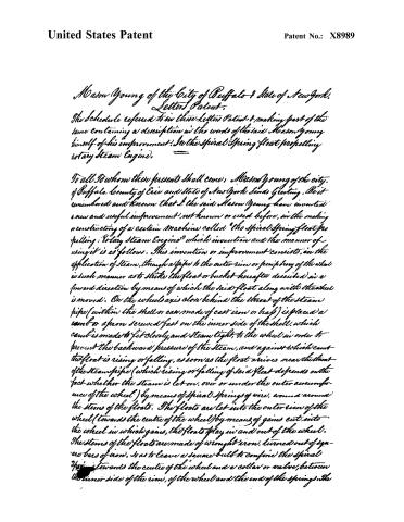
Mason Young of the City of Buffalo & State of New York.
Letters Patent.
The Schedule referred to in these Letters Patent & making part of the same containing a description in the words of the said Mason Young himself of his improvement: In the Spiral Spring Float propelling rotary Steam Engine.
To all To whom these presents shall come, Mason Young of the city of Buffalo, County of Erie and State of New York Sends Greeting. Be it remembered and known that I the said Mason Young have invented a new and useful improvement, not known or used before, in the making or constructing of a certain machine called “the Spiral Spring Float propelling Rotary Steam Engine” which invention and the manner of using it is as follows. This invention or improvement consists, in the application of Steam, through a pipe to the outer rim or periphery of the wheel in such manner as to strike the float or bucket hereafter described in a forward direction by means of which the said float along with the wheel is moved. On the wheel axis close behind the throat of the steam pipe (within the shell or case made of cast iron or brass) is placed a cam or apron screwed fast on the inner side of the shell, which cam is made to fit closely, and steam tight, to the wheel in order to prevent the backward pressure of the steam, and against which cam the float is rising or falling, as soon as the float arrives near the throat of the steam pipe (which rising or falling of said float depends on the fact whether the steam is let on, over or under the outer circumference of the wheel) by means of spiral springs of wire, wound around the stems of the floats. The floats are let into the outer rim of the wheel (towards the centre of the wheel) by means of gains cut into the wheel in which gains, the floats play in and out of the wheel. The stems of the floats are made of wrought iron, turned out of square bars of iron, so as to leave a square bulb to confine the spiral springs towards the centre of the wheel and a collar or valve, between the inner side of the rim, of the wheel and the end of the springs. The
Page 3.
United States Patent
Patent No.: X8989
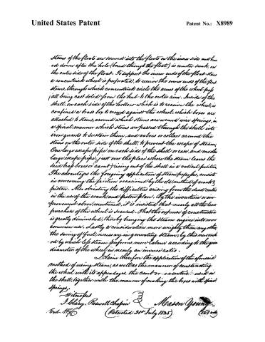
Stems of the floats are screwed into the floats on the inner side and headed down after the hole (bored through the float) is counter sunk, on the outer side of the float. To support the inner ends of the float-stems a concentric wheel is perforated, to receive the inner ends of the float-stems, through which concentric circle the arms of the wheel pass (all being cast solid) from the hub to the outer rim. Inside of the shell, on each side of the hollow which is to receive the wheel, is confined a brass box to crowd against the wheel, which boxes are attached to stems, around which stems are wound wire springs, in a spiral manner which stems are passed through the shell into iron guards to sustain them, and valves or collars around the stems on the outer side of the shell, to prevent the escape of steam. One large escape pipe on each side of the shell or case, and another large escape pipe, just over the place where the steam leaves the said brass boxes or cams) rising out of the shell in a vertical position. The advantages the foregoing application of steam propellers, consist in overcoming the friction occasioned by the old method of crank & piston. Also obviating the difficulties arising from the dead centres in the use of the crank and piston plan. By the invention or improvement above mentioned, it is insisted that nearly all the lever purchase of the wheel is secured. That the expense of construction is greatly diminished, thereby bringing the steam engine into more common use. Lastly a consideration more weighty than any other, the saving of fuel, necessary in generating steam; by this new method by which less steam performs more labour according to the given diameter of the wheel in nearly an inverse ratio.
I claim therefore the application of the aforesaid method of using steam, as well as the manner of constructing the wheel with its appendages, the cam or eccentric used in the shell, together with the manner of making the boxes with spiral springs.
Witnesses
J. Blary. Roswell Chapin
Mason Young
Patented 21st July 1825
About this record
- Patentee
- DATAMP, Burke's List of Patents (1847)
- Date
- the Name and Date index of patents, DATAMP, USPTO records
- Invention
- DATAMP
- Listed in
- the Name and Date index of patents, DATAMP, USPTO records, Jim Shaw's X-patent list, Burke's List of Patents (1847)
- The name conflict was settled by Burke's 1847 list.
- Burke's 1847 Patent Office list gives the same patent.
Shaw: lists Herrick, W A here as 8989½