

Drawings and documents
National Archives restored drawings: drawing
Joseph Turner's Patent Drawing for a Machine for Churning Butter

National Archives, Restored Patent Drawings (Record Group 241) · Full-size scan at the National Archives · Catalog record
Show the text on the drawing Hide (35 words)
Words on the drawing as machine-read by the National Archives; not checked. Useful mainly for searching.
31 / End 31 / 31. DAIRY / Reclprocating Churns, / and will iffore / 180 / Lever Mechanism, / Multiple Dash / age products / 90034 / DIVISIONS / 82 / Machin for churning Buller. / Ge
USPTO scan
The patent as scanned by the USPTO
-
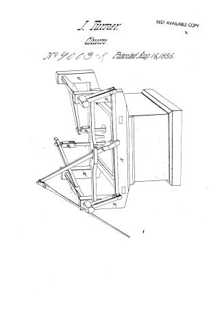 Page 1
-
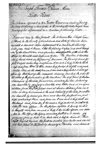 Page 2
-
 Page 3
-
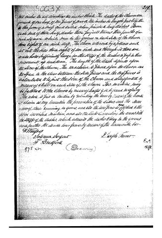 Page 4


U.S. Patent and Trademark Office · Google Patents
Show the transcription Hide (1,122 words)
Machine transcription (LightOnOCR) of the pages as scanned by the USPTO, most of them the handwritten copies made when the records were restored after the 1836 fire. Not checked; it can misread handwriting, so compare it with the scan.
Page 1.
J. Turner.
Churn.
No 4003-X Patented Aug. 15, 1835.
BEST AVAILABLE COPY
Page 2.
Aug 18, 1855
Joseph Turner & Anna Mann
Setters Patent
The Schedule referred to in this Letters Patent and making part of the same containing a description in the words of the said Joseph Turner himself of his improvement in a machine for churning butter.
Know all men by these presents. Be it known that Joseph Turner & Anna in the County of Cumberland and State of Maine have invented a new and useful improvement in a machine for churning butter from milk & cream, & that the following is a full and exact description of the Construction and operation of the said Machine as invented and improved by me. The Machine is constructed of hard wood in the following Manner. The pieces of wood two feet & eight inches long and from one to one and a half inches in thickness and from three to three and a half inches in depth and grain slanted towards the ends from one to one and a half inches at side up & down by that part of the unopened drawing marked A forms the two sides of the foundation of the Machine. The top pieces of the same dimensions of the side pieces above described front and sides long are inserted by means of a Mortise and tenon each at an equal distance from the side pieces and at such a distance from each other as may be convenient. On each extremity of the side pieces there are inserted by means of a tenon and Mortise for posts one foot high exclusive of tenon and from one to one and a half inch in thickness and from two to two and a half inches in width as by letter (B) will appear. The Shafts from eighteen to twenty inches in length and from one and a half to two inches square are inserted in the top of the before described posts so as to revolve on guides from one inch to an inch and a half in diameter. These Shafts project beyond the posts one and one half inches and are let into their place in the posts by means of a Mortise and tenon
Page 3.
By a follower & key. On the projecting ends of the shafts there are mounted by means of a tenon and mortise two arms eight inches long exclusive of mortise one inch and a half square. These arms when the machine is not in motion fall parallel with that of the two posts. In the base of each of these are mortises three fourths of an inch in width into which there is inserted a bar of the same thickness of the mortise & an inch and a half wide connecting the two arms and forming a joint. A wood or iron pin fastens the end of the bar to the extremity of the arms as will appear by the letter C. Another bar exactly as the one described is immovably fixed to the two posts parallel with the other. When the machine is stationary, through which there is a mortise two inches wide & 4 long as by letter (E). A lever from three to four feet long and two inches square is then connected with the movable bar by means of mortise in said bar fastened by a wood or iron pin. It also forms a joint and being inserted through the immovable bar is there fastened by a wood or iron pin also. This last forms the fulcrum as will be seen at letter (F). A handle from four to six feet long is attached by means of a joint to the upper end of the lever as per letter (G). In the shafts half way between the posts are inserted two long cones square and immovable horizontally so as nearly to meet. These arms are two inches square and near the ends are inserted by means of a mortise in the same two connectors or links the upper part of which is formed by a tenon and the lower part by a mortise. These are connected to the arms by means of a pin and form a joint and are about four inches in length including the tenon and mortise as will appear by the letter (H). To the lower part of this link or connector is attached the staff of the Chain block or spring vice which are alike. The Chain to which the above machinery is applied is constructed as follows: A by one foot square and from eighteen inches to two feet in height constitutes the Chain. This is made of pine plank or board one inch and a quarter thick lashed together at the corners. This stands on a plank bottom projecting
Page 4.
two inches in all directions two inches thick. The sides of the Churn are formed of one half of the pieces of wood ten inches in length put together in the form of a roof and called when finished a half dasher. About each end of these half dashers there projects towards the fourth of an inch square which runs in the grooves on each side of the Churn three eighths of an inch deep. The Churn is bored by a follow and cut into the side three eighths of an inch and through it there are made holes sufficiently large for the staffs of the dashers to pass in their movements up and down. The length of the dasher depends upon the size of the Churn. The machine is placed upon the Churn and the space in the clear between the side pieces and the top piece is calculated to be just the size of the Churn and is supported by means of cleats on each side of the Churn. This machine may be fastened to the Churn by means of hafts if it is found necessary. The whole is put in motion by vibrating the lever by means of the handle or chain as my invention the formation of the dasher and the manner of their running in grooves, and also the lever power as applied to the above described machine, and also the links connecting the arms with the staffs of the dashers, which admits the dashers to stay in the grooves and fasten the dasher lever power by means of the immovable bar.
Witnesses
Selena Sorgent
H. Bradford
Joseph Turner
975 w/o
(Drawing)
Ex. 4.
Off.
Published accounts: journal notice
Notice in the monthly list of patents
Journal of the Franklin Institute, new ser., vol. 16 (1835), p. 286 · View the page
443. Churn.-Joseph Turner, Portland, Maine,
Published accounts: journal notice
Notice in the monthly list of patents, with remarks
Journal of the Franklin Institute, new ser., vol. 17 (1836), p. 195 · View the page
3. For a Churn; Joseph Turner, Poland, Cumberland county, Maine, August 15.
Remarks. This churn has a formidable array of levers, rods, and connecting joints, by which two dashers are to be worked up and down in an oblong square box; we do not think it worth the space which would be required to describe it, or to furnish the claim; the former would show a complex mode of effecting that which has been repeatedly, and as well, done by more simple means; and the latter a variety of mistakes in supposing old things to be new.
DATAMP: illustration
Illustrations from DATAMP
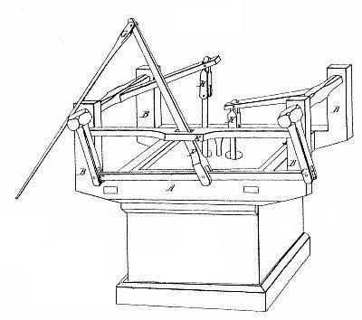

DATAMP (Directory of American Tool and Machinery Patents), via the Internet Archive · Archived DATAMP page
About this record
- Patentee
- DATAMP
- Date
- DATAMP, USPTO records, Burke's List of Patents (1847)
- Invention
- DATAMP
- Listed in
- the Name and Date index of patents, DATAMP, USPTO records, Jim Shaw's X-patent list, the Journal of the Franklin Institute, Burke's List of Patents (1847)
- The sources give different dates; the date shown is the one most of them agree on.
- The Franklin Institute's journal confirms the date shown.
- Burke's 1847 Patent Office list gives the same patent.