

Drawings and documents
National Archives restored drawings: drawing
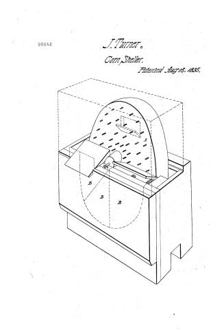
Joseph Turner's Patent Drawing for a Corn Sheller

National Archives, Restored Patent Drawings (Record Group 241) · Full-size scan at the National Archives · Catalog record
Show the text on the drawing Hide (18 words)
Words on the drawing as machine-read by the National Archives; not checked. Useful mainly for searching.
/9 / .T / OIR
USPTO scan
The patent as scanned by the USPTO
-
 Page 1
-
 Page 2
-
 Page 3
-
 Page 4


U.S. Patent and Trademark Office · Google Patents
Show the transcription Hide (1,055 words)
Machine transcription (LightOnOCR) of the pages as scanned by the USPTO, most of them the handwritten copies made when the records were restored after the 1836 fire. Not checked; it can misread handwriting, so compare it with the scan.
Page 1.
9004X
J. Turner,
Corn Sheller.
Patented Aug 15, 1835.

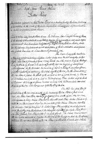
Page 2.
Aug 15, 1855
Joseph T. Stone, Maine
Letters Patent
The Legislature referred to in the Letters Patent and making part of the same containing a description in the words of the said Joseph T. Stone, his improvement in a machine called a Corn Sheller.
That to have the present State Corn Sheller, be it known that Joseph T. Stone of Plume in the county of Cumberland and State of Maine, have invented a new and useful improvement in a machine designated by the term called the Corn Sheller, and that the following is a full and exact description of the Construction and operation of said machine as invented or improved by me.
The lower body of the machine is three feet eight inches long, eighteen inches wide and two feet and six inches high. This box is formed of hard wood plank one inch and a half in thickness and is fastened by screws to a base or foot the feet are half long and four inches square in the corners. In the side of this box there is an open space of eight inches high extending the whole length of the box, in the same side of the box there is fitted the posts in the corners a bar of hard wood, to turn or rotate one inch and a half in thickness and three inches deep in such a manner as to leave a space one and a half inch between said bar and the side of the box. This bar comes up to the top of the box.
On this bar and the top of the box and exactly in the middle of the box there is put a bar iron, on this bar there is made a quantity of iron made of one inch by one inch square a heavy wheel three feet in diameter and three inches thick as by letter A in the annexed drawing. On one side of this wheel there are inserted six circular rows of iron pins, the inches long three eighths of an inch square and projecting from the surface of the wheel for eight inches in width. These pins are thus placed from three to three inches apart. The wheel has as near the bar above described as possible, on the side of the iron and in the space between the bar and the side of the box there is fastened a small iron wheel
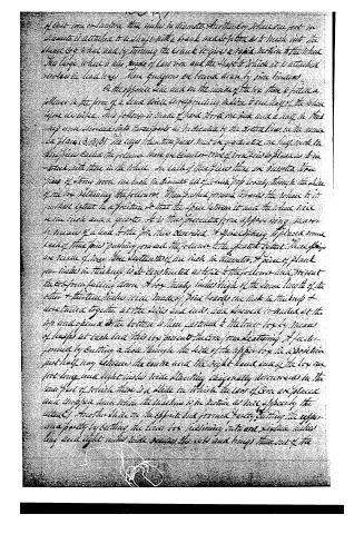
Page 3.
of cast-iron or bar-iron, three inches in diameter. The two eye-plates are put in diameter is attached to a shaft with a crank made fitted so as to work into the space of a wheel and by turning the crank it gives a rapid motion to the wheel. The large wheel is also made of cast-iron and the shaft to which it is attached works in lead-holes. These eyeglasses are formed down by fine lines.
On the opposite side and on the inside of the box there is fitted a follower in the form of a drum with corresponding ridges to the shape of the wheel before described. This follower is made of black iron one inch and a half in thickness and is divided into three parts as indicated by the dotted lines on the inner diagram (3). (3). (3). The upper of these pieces must be graduated so as to keep in the three pieces called the followers there are similar to those in the diagram so as to be in touch with those in the wheel. In each of these pieces there are inserted three pieces of strong iron one inch in diameter all of which pass loosely through the side of the box retaining the followers. These pieces are formed to enclose the wheel in its position except in a position so that the space between it and the wheel will be one inch and a quarter. It is thus prevented from slipping being secured by means of a lead to the pin thus described. A piece of iron is placed some back of these pins pushing forward the followers to the greatest extent. These pins are made of iron three eighths of an inch in diameter, a piece of black iron inches in thickness, well constructed so as to fit to the followers and prevent the box from falling down. A box nearly inches high of the same length of the other + thirteen inches wide made of iron nearly one inch in thickness and nailed together at the sides and ends, and screwed or nailed at the top and opened at the bottom is then fastened to the lower box by means of hoops at each end. This box prevents the iron from scattering. A hole is formed by cutting a hole through the side of the upper box in a direction just half way between the centre and the right hand end of the box one foot long and eight inches wide slanting diagonally downwards in the line of the wheel there is a plate on which the box of iron is placed and a spring which when the machine is in motion will operate by the action of another plate on the opposite box prevents partly cutting the upper and partly by cutting the lower box inclining outward, a piece of iron being one inch and eight inches wide between the ends and brings them out of the
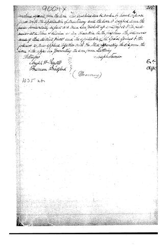
Page 4.
90011 X
machine separate from the cone. This machine can be worked by hand or horse power. With the application of machinery and the cone is dropped down the paper horizontally so fast so a man can pick it up and drop it to the feeder.
several at a time. Claims as the invention is the feeding the followers made of three distinct pieces and the application of the special springs to the followers as now applied together with the slide separating the cone from the cone and the upper bar preventing the cone from starting.
H. H. H.
Joseph H. Pratt
Thomas Bradford
(Drawing)
1035 w.
Ex.
Clyr.
215
Published accounts: journal notice
Notice in the monthly list of patents
Journal of the Franklin Institute, new ser., vol. 16 (1835), p. 286 · View the page
444. Corn sheller.-Joseph Turner, Portland, Maine,
Published accounts: journal notice
Notice in the monthly list of patents, with remarks
Journal of the Franklin Institute, new ser., vol. 17 (1836), p. 195 · View the page
4. For a Machine for Shelling Corn; Joseph Turner, Poland, Cumberland county, Maine, August 15.
Remarks. A vertical wheel, set with pins upon its face, is to be made to revolve, and the shelling is to be effected between this wheel, and a follower borne up towards it by spiral springs. There is nothing in the particular arrangement of the follower, as claimed by the patentee, to render it better than the analogous contrivances which have been used in the machines with vertical wheels of cast-iron. The claim is to "the follower, as made in three distinct pieces, and the application of the spiral springs to the follower, together with the slide separating the cob from the corn." This latter claim, so far as we can understand it, is for a thing without any novelty; but as it is not represented in the drawing, and the latter has no written references whatever upon it, a little obscurity may be expected.
DATAMP: illustration
Illustrations from DATAMP


DATAMP (Directory of American Tool and Machinery Patents), via the Internet Archive · Archived DATAMP page
About this record
- Patentee
- DATAMP
- Date
- DATAMP, USPTO records, Burke's List of Patents (1847)
- Invention
- DATAMP
- Listed in
- the Name and Date index of patents, DATAMP, USPTO records, Jim Shaw's X-patent list, the Journal of the Franklin Institute, Burke's List of Patents (1847)
- The sources give different dates; the date shown is the one most of them agree on.
- The Franklin Institute's journal confirms the date shown.
- Burke's 1847 Patent Office list gives the same patent.