

Drawings and documents
USPTO scan
The patent as scanned by the USPTO
-
 Page 1
-
 Page 2
-
 Page 3
-
 Page 4
-
 Page 5


U.S. Patent and Trademark Office · Google Patents
Show the transcription Hide (1,519 words)
Machine transcription (LightOnOCR) of the pages as scanned by the USPTO, most of them the handwritten copies made when the records were restored after the 1836 fire. Not checked; it can misread handwriting, so compare it with the scan.
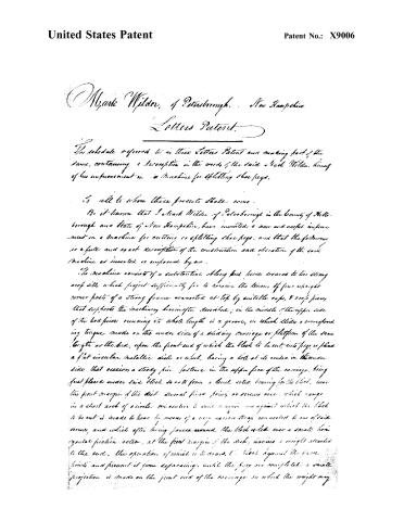
Page 2.
United States Patent
Patent No.: X9006
Mark Wilder, of Peterborough, New Hampshire
Letters Patent.
The schedule offered to in these Letters Patent and making part of the same, containing a description in the words of the said Mark Wilder himself of his improvement in a Machine for splitting shoe pegs.
To all to whom these presents shall come.
Be it known that I Mark Wilder of Peterborough in the County of Hillsborough and State of New Hampshire, have invented a new and useful improvement in a Machine for cutting or splitting shoe pegs, and that the following is a full and exact description of the construction and operation of the said Machine as invented or improved by me.
The machine consists of a substantial oblong bed piece secured to two strong cross bars which project sufficiently far to receive the tenons of four upright corner posts of a strong frame connected at top by suitable caps, & cross pieces, that supports the machinery herein after described; in the middle of the upper side of the bed piece running its whole length is a groove, in which slides a corresponding tongue made on the under side of a sliding carriage or platform of the same length as the bed, upon the front end of which the block to be cut, into pegs, is placed a flat circular metallic disk or wheel, having a hole at its centre in the under side that receives a steady pin fastened in the upper face of the carriage, being first placed under said block so as to form a level solid bearing for the block, near the front margin of the disk several fixed pins or screws are, which range in a short arch of a circle concentric to said margin and against which the block to be cut is made to bear by means of a very narrow strap connected to one of said screws, and which after being passed around the block is led over a small horizontal friction roller, at the front margin of the disk, having a weight attached to the end, the operation of which is to draw, the block against the firm limits and prevent it from separating, until the peg are completed, a small projection is made on the front end of the carriage on which the weight may
Page 3.
United States Patent
Patent No.: X9006
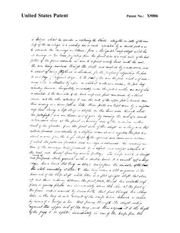
a. loaded whilst the operator is replacing the blocks, along the middle of the rear half of the carriage is a safety bar or rack operated by a double pallet so as to advance the carriage as follows; from a horizontal crop shaft which has its bearings in two boxes projecting from the front side of a crop rail of the back portion of the frame descends an arm to a point nearly level with the rack, the arm being mortised through the shaft, and confined by a side screw, so as to admit of being lengthened or shortened, for the purpose of adjusting the feed to suit pegs of different sizes. To the foot of the arm the pallet which is of ordinary make is attached by a pin on which it works as a center, the pallet itself extending forward, horizontally, immediately under this pallet is another one end of which is attached to the lower side of the back crop rail first mentioned by a thumb screw, and the other extending to near the end of the upper pallet is turned down thus serving as a lower pallet or hold, these pallets are kept down by a weighted crop lever having a left strap or staple on the lower side through which the pallets pass, and are thrown out of gear by raising the end of a second or transversal lever at the front or leading side of the machine within reach of the operator, from the front side of the shaft is a long arm that extends forward and attaches by a sliding screw so as to regulate the feed to a third or arm from the knife shaft by the upward and downward motions of which the pallets are operated and carriage is advanced, the receding motion of the carriage being produced by a cord and weight attached to the back end thereof operating over a pulley. The knife which is straight made of and tempered steel, ground with a double bevel to a smooth not a sharp edge, has a broad flat tang or strap rising from the middle of the back the whole resembling a letter T this tang enters a slot or groove in the lower end of the knife shaft which latter is a flat upright shaft that slides up and down midway between the front posts, through two suitable crop pieces or guides placed one immediately above the other at the front of the frame and is secured by screw bolts, that pass through two oblong holes in the tang so as to admit of the knife being lowered or raised by means of a wedge or key that passes through the shaft acting against the upper end of the tang, and thus adjust it to the length of the pegs to be split, immediately in rear of the knife from the
Page 4.
United States Patent
Patent No.: X9006
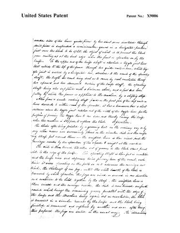
under side of the lower guide piece by two short arms inserted through said piece is suspended a semicircular guard in a horizontal position just over the block to be split, the object of which is to prevent the block from coming up at the back edge when the front is operated on by the knife. To the upper end of the knife shaft is attached a toggle joint lever that extends to the top of the frame through two guide rails or bars, which toggle joint is worked by a horizontal bar, attached to the crank of the operating shaft, the length the crank being such as to cause by each revolution thereof two upward and two downward motions of the knife shaft, the operating shaft being also supplied with a balance wheel, and a fast and loose pulley by which the power is applied to the machine, by a slipping strap also from a small rocking shaft fixed on the front face of the cap rail a lever descends to within reach of the operator, it has a transverse bar a short distance above the toggle joint notched out of the width of the toggle lever, for the purpose of forcing the toggle lever to one side, and thereby raising the knife when the machine is stopped, to replace the block. Operation.
The blocks after being pointed by a graining tool in the ordinary way or by any other means are successively placed on the circular disk and the confining strap put around them — the weighted lever is then raised, and the carriage recedes by the operation of the chord & weight at the rear end.
The disk is then turned till either set of grooves in the block stands parallel to the edge of the knife. The operating shaft is then put in revolution and the knife rises and descends twice for every turn of the crank, each time it rises operating on the path so as to advance the carriage and block, the thickness of one peg, until the whole breadth of the block is traversed by which operation the pegs are raised or scored in one direction and continue to be held together by the strap, the weighted lever is then raised and the carriage recedes, the disk is now turned one fourth round which brings the remaining grooves parallel with the edge of the knife and the machine being again set in revolution, the block is traversed in a similar manner by the knife and the block being finished is removed and replaced by another and so on. After being thus prepared the pegs are sorted in the usual way. The dimensions
Page 5.
United States Patent
Patent No.: X9006
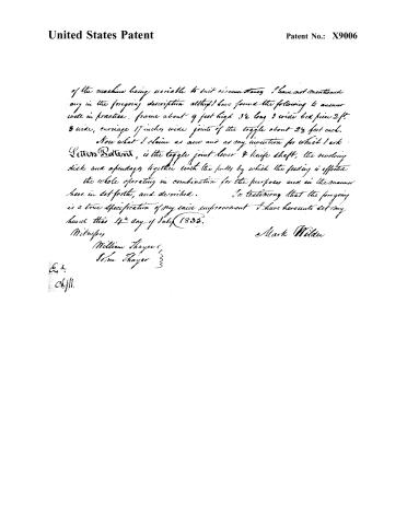
of the machine being variable to suit circumstances I have not mentioned any in the foregoing description although I have found the following to answer well in practice, frame about 9 feet high 3½ long 3 wide bed piece 2 ft. 3 wide, carriage 17 inches wide joints of the toggle about 2½ feet each.
Now what I claim as new and as my invention for which I ask Letters Patent, is the toggle joint lever & knife shaft, the revolving disk and apendages together with the pulleys by which the feeding is effected the whole operating in combination for the purposes and in the manner here in set forth, and described. In testifying that the foregoing is a true specification of my said improvement I have hereunto set my hand this 14th day of July 1833.
Witnesses
William Thayer
Wm Thayer
Mark Wilder
E.1.
ckjll.
Published accounts: journal notice
Notice in the monthly list of patents
Journal of the Franklin Institute, new ser., vol. 16 (1835), p. 286 · View the page
451. Shoe pegs, splitting.-Mark Wilder, Peterborough, N. Y.
Published accounts: journal notice
Notice in the monthly list of patents, with remarks
Journal of the Franklin Institute, new ser., vol. 17 (1836), p. 196 · View the page
10. For a Machine for Splitting Shoe Pegs; Mark Wilder, Peterborough, Hillsborough county, New Hampshire, August 15.
Remarks. A vertical frame has, at its lower end, a cutting knife for cutting the pegs, which knife is attached to a vertical slide, that is operated upon by a toggle joint, worked by a bar, or pitman, in the usual way. The blocks, after having been pointed by a grooving tool, are placed upon a sliding bed below the knife, where they are secured upon a metallic disk adapted to receive them. The sliding bed is made to advance by the action of a feed rod, which receives its motion from that of the toggle joint, and slide. The grooved block must, of course, be adjusted to the knife, and must also be surrounded by a strap, to keep the rived parts together. The claim is, to "the toggle joint, lever, and knife shaft, the revolving disk, and appendages, together with the palls by which the feeding is effected, the whole operating in combination for the purposes, and in the manner, herein set forth and described." The claiming of the toggle joint, palls, &c., separately, is not a safe course, as they are not the invention of the patentee; yet, by a fair construction of the foregoing, they are claimed individually, as well as in combination.
About this record
- Patentee
- DATAMP
- Date
- DATAMP, USPTO records
- Invention
- DATAMP
- Listed in
- the Name and Date index of patents, DATAMP, USPTO records, Jim Shaw's X-patent list, the Journal of the Franklin Institute, Burke's List of Patents (1847)
- The sources give different dates; the date shown is the one most of them agree on.
- The Franklin Institute's journal confirms the date shown.
- Burke's 1847 Patent Office list gives the same patent.