

Drawings and documents
National Archives restored drawings: drawing
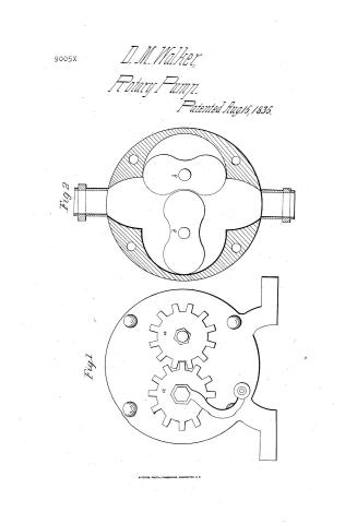
David M. Walker's Patent Drawing for a Hydraulic Pump

National Archives, Restored Patent Drawings (Record Group 241) · Full-size scan at the National Archives · Catalog record
Show the text on the drawing Hide (84 words)
Words on the drawing as machine-read by the National Archives; not checked. Useful mainly for searching.
103. 15 PUR. / Rotary / Double Piston. / Jas / 9005-1 / DIVISION: / Hydraulic Pump. / Patented any 15th 1835. / got / Fig. 1. / Preference Fig - Frontiero of one of the heads a. a the cog wheels. / tig - section of the shell and circular floats b b. / Patent office the ii November 180g / made under the direction of the Gom migionir of Patents / in conformity with act of 3rd march 1837 / M / Piltworth / you / in of fetents
USPTO scan
The patent as scanned by the USPTO
-
 Page 1
-
 Page 2
-
 Page 3


U.S. Patent and Trademark Office · Google Patents
Show the transcription Hide (619 words)
Machine transcription (LightOnOCR) of the pages as scanned by the USPTO, most of them the handwritten copies made when the records were restored after the 1836 fire. Not checked; it can misread handwriting, so compare it with the scan.
Page 1.
9005X
D. M. Walker,
Rotary Pump.
Patented Aug 15, 1835.
Fig. 2
Fig. 1
Page 2.
Aug 13, 1835
David M. Walker, of Cavendish, State of Vermont
Letters Patent.
The schedule referred to in these Letters Patent and making part of the same containing a description in the words of the said David M. Walker, himself of his improvement in the Rotary Hydraulic Pump,
To all to whom these presents shall come,
Be it known that I David M. Walker of Cavendish in the county of Windsor, and State of Vermont, have invented a new and useful improvement in the Rotary Hydraulic Pump, and the following is a full and exact description of the construction and operation of the said machine as proposed by me, it being an improvement on "Hubbard's rotary Pump" of which the following is a correct description to wit:—
Hubbard's pump consists of a cast iron shell, perfectly circular with flat sides or ends. Within the shell are two cylinders, each containing eight curved floats, which mesh together during the revolutions of the cylinders, or during the operation of the pump, which revolutions of the cylinders, or operation of the pump is effected by means of a crank attached to the end of the arbor of one of the cylinders which in revolving comes in contact with the other cylinder and propels it. The revolutions of the cylinders produce a vacuum which is immediately filled with water through the orifice in the bottom, which water is thrown out at the top by the continued revolutions of the cylinders with their floats. The external appearance of mine is similar to Hubbard's, with the exception of two small cog wheels fitted to the end of the arbor of each cylinder. Its internal parts consist of two cylinders, each of which has two wings or circular floats only, fitted to an exact circle on the inside of the shell, and also to mesh one into the other in the operation of the pump. The small cog wheels on the outside of the pump are so arranged that by means of them on a crank the said cylinders are propelled and the collision or friction of the cylinders is obviated. Another advantage which this possesses is, the cylinders lock closer and exclude more of the atmospheric air from the tube below, and consequently will produce a vacuum with ease. It is also simple in its construction internally and not-
Page 3.
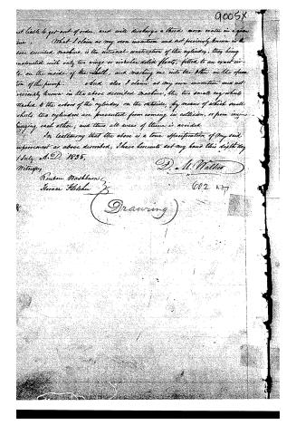
at liable to get out of order, and will discharge a third more water in a given time. What I claim as my own invention and not previously known in the above described machine, is the internal construction of the cylinders, they being constructed with only two wings or circular solid floats, fitted to an exact circle on the inside of the shell, and making one into the other in the operation of the pump. And also I claim as my own invention and not previously known in the above described machine, the two small cog wheels attached to the axles of the cylinders on the outside, by means of which small wheels the cylinders are prevented from coming in collision, or from impinging each other; and thus all wear of them is avoided.
In testimony that the above is a true specification of my said improvement as above described, I have hereunto set my hand this sixth day of July A.D. 1835.
D. A. Walter
Witnesses:
Reuben Washburn
Horace Fletcher
(Drawing)
Published accounts: journal notice
Notice in the monthly list of patents
Journal of the Franklin Institute, new ser., vol. 16 (1835), p. 286 · View the page
452. Rotary pump.-David M. Walker, Cavendish, Vermont,
Published accounts: journal notice
Notice in the monthly list of patents, with remarks
Journal of the Franklin Institute, new ser., vol. 17 (1836), p. 197 · View the page
11. For an improvement in Hubbard's Rotary Pump; David M. Walker, Cavendish, Windsor county, Vermont, August 15.
Remarks. This might as well have been called an improvement upon a dozen other rotary pumps, as upon Hubbard's. Like the rotary pumps which have preceded it, it is difficult to make, and of little worth after it is made, as its operation depends upon the fitting of revolving pieces of metal to the interior of a drum, or cylinder, in which they revolve. Had the patentee been acquainted with the history of rotary pumps, as they have been known for upwards of a century, he would not have placed this upon record.
About this record
- Patentee
- DATAMP
- Date
- DATAMP, USPTO records, Burke's List of Patents (1847)
- Invention
- DATAMP
- Listed in
- the Name and Date index of patents, DATAMP, USPTO records, Jim Shaw's X-patent list, the Journal of the Franklin Institute, Burke's List of Patents (1847)
- The sources give different dates; the date shown is the one most of them agree on.
- The Franklin Institute's journal spells the name differently.
- The Franklin Institute's journal confirms the date shown.
- Burke's 1847 Patent Office list gives the same patent.