

Drawings and documents
National Archives restored drawings: drawing
C. Angerine's Patent Drawing for a Churn

National Archives, Restored Patent Drawings (Record Group 241) · Full-size scan at the National Archives · Catalog record
Show the text on the drawing Hide (75 words)
Words on the drawing as machine-read by the National Archives; not checked. Useful mainly for searching.
31. DAIRY. / Reciprocating Churns. / Crank Mechanism. / Single Dasher. / classIFICATION / ox / 9009. it / DIVISION. / C. AN GERINE / 82 / ChurnD. / Patenled 17" laug. 1835 / u. Platgorne / b. gallows grame / C. Walking beam / d. chemus / e. Pendulous Lever / f. Pitman.9 crank - -h. Fly wheel / OF / Patent 1843 / Made under the directions ? the commonent of Patents / in comformity with act of 3 March 1837 / Wd summth / Commercracen of Patail
USPTO scan
The patent as scanned by the USPTO
-
 Page 1
-
 Page 2
-
 Page 3


U.S. Patent and Trademark Office · Google Patents
Show the transcription Hide (557 words)
Machine transcription (LightOnOCR) of the pages as scanned by the USPTO, most of them the handwritten copies made when the records were restored after the 1836 fire. Not checked; it can misread handwriting, so compare it with the scan.
Page 1.
9009X
C. Angerine,
Churn.
Patented Aug. 17, 1835
NO PRINTED SPECIFICATION AVAILABLE
Page 2.
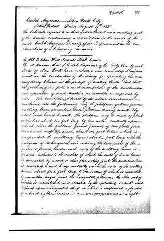
Caleb Angerine — New York City
Letters Patent, Dated August 17th 1835
The Schedule referred to in these Letters Patent and making part of the same containing a description in the words of the said Caleb Angerine himself of his Improvement in the construction of a churning machine
To All to Whom These Presents Shall Come:
Be it known that I Caleb Angerine of the City, County and State of New York have invented a new and useful improvement in the construction of machinery for operating the ordinary dairy churn in the process of making Butter And that the following is a full & exact description of the construction and operation of said Machine as invented or improved by me. The constituent parts of the above mentioned machine are the following viz A platform, gallows frame, walking beam, pendulous lever, pitman, driving crank, fly wheel and hand crank. The platform may be made of plank or timbers about six feet long by two wide, centrally upon which rides the gallows frame formed of two posts, four braces and cross top piece, about one foot below which is suspended the walking beam about feet long with the quadrants of its horizontal axis entering the side posts of the gallows frame, Under each end of the walking beam is placed a churn to the dashers of which the ends of said beam is connected by a cord or other free acting joint. The pendulous lever is mortised to and hangs centrally under the axis of the walking beam about four feet long, to the bottom of which is connected by an active tongue joint the horizontal pitman, the other end of which is attached to and operated by the operating crank, which is fixed upon a horizontal shaft on which is suspended a fly wheel of about eighteen inches in diameter proportioned in weight
Page 3.
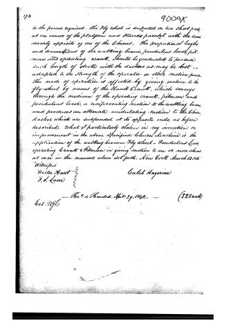
to the power required. The fly wheel is supported on two short posts, at one corner of the platform and stands parallel with the same nearly opposite of one of the columns. The proportional lengths and dimensions of the walking beam, pendulous lever, pitman and operating crank, should be graduated to produce such length of stroke with the dashing as may be best adapted to the strength of the operator or other motive power. The mode of operation is effected by giving motion to the fly-wheel by means of the hand crank, which conveys through the medium of the operating crank, pitman and pendulous lever, a reciprocating motion to the walking beam, and produces an alternate undulating motion to the column dashing, which are suspended at its opposite ends, as before described. What I particularly claim in my invention or improvement in the above specified column machine is the application of the walking beam—fly wheel—pendulous lever, operating crank & pitman in giving motion to one or more columns at once in the manner above set forth. New York March 22, 1855.
Witnesses
Walter Hunt
J. J. Lane
Caleb Angerine
Rec'd & Recorded April 29, 1855. (528 words)
Exd. 1856
Published accounts: journal notice
Notice in the monthly list of patents
Journal of the Franklin Institute, new ser., vol. 16 (1835), p. 286 · View the page
463. Churn.-Caleb Angerine, city of New York, List of American Patents for August, 1835.
Published accounts: journal notice
Notice in the monthly list of patents
Journal of the Franklin Institute, new ser., vol. 16 (1835), p. 287 · View the page
464. Harpoon.-Caleb Angerine, city of Boston,
Published accounts: journal notice
Notice in the monthly list of patents, with remarks
Journal of the Franklin Institute, new ser., vol. 17 (1836), p. 200 · View the page
22. For a Churn; Caleb Angerine, City of New York, August 17.
Remarks. Mr. Angerine obtained a patent for a churn some time ago, and although he has a new patent he has not a new churn, as this last is a fac simile of such as were previously on the shelves of the patent office. Two churns of the ordinary kind are placed upon a platform, the two dashers are attached to a vibrating beam, to which motion is communicated by a crank, aided by a fly wheel. The patentee claims "the application of the walking beam, fly wheel, pendulous lever, operating crank and pitman, in giving motion to one or more churns at once.
About this record
- Patentee
- DATAMP
- Date
- DATAMP, USPTO records, Burke's List of Patents (1847)
- Invention
- DATAMP
- Listed in
- the Name and Date index of patents, DATAMP, USPTO records, Jim Shaw's X-patent list, the Journal of the Franklin Institute, Burke's List of Patents (1847)
- The sources give different dates; the date shown is the one most of them agree on.
- The Franklin Institute's journal spells the name differently.
- The Franklin Institute's journal confirms the date shown.
- Burke's 1847 Patent Office list gives the same patent.