

Drawings and documents
National Archives restored drawings: drawing
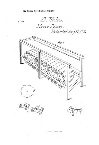
Benjamin Wales' Patent Drawing for Endless Chain Horse Power

National Archives, Restored Patent Drawings (Record Group 241) · Full-size scan at the National Archives · Catalog record
Show the text on the drawing Hide (34 words)
Words on the drawing as machine-read by the National Archives; not checked. Useful mainly for searching.
185. MECHANICAL MOTORS. / Horse-Powers, / Treads. / JAMIN WALESSS / ENDLESS CHAIN HORSE POWER / classification / Patented / 9035.1 / DIVISION / Fig. A. / 3. / B. / C. / D.
USPTO scan
The patent as scanned by the USPTO
-
 Page 1
-
 Page 2
-
 Page 3


U.S. Patent and Trademark Office · Google Patents
Show the transcription Hide (900 words)
Machine transcription (LightOnOCR) of the pages as scanned by the USPTO, most of them the handwritten copies made when the records were restored after the 1836 fire. Not checked; it can misread handwriting, so compare it with the scan.
Page 1.
No Printed Specification Available
9038X
B. Wale's,
Horse Power.
Patented Aug. 17, 1835.
Fig. A.

A.M. PHOTO-LITHO. CO. N.Y. (OSBORNE'S PROCESS)
Page 2.
Aug 17 1833
Benjamin Wates D. Hallowell Maine
Sellers Patent
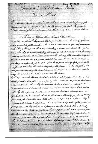
The schedule referred to in their Sellers Patent and making part of the
same containing a description in the words of the said Benjamin
Wates Junior of his improvement in the cutlet Chain Horse Power
To all to whom these presents shall come
Be it known that Benjamin Wates of Hallowell in the County of Aroostock
and State of Maine have invented a new and useful improvement
in the "Horse Power" and that the following is a full and exact description
thereof. Fig 1 of the accompanying drawings which are referred to and
made a part of this description represent the whole of this machine ready for
operation and consists of a frame which has four horizontal bars three
four long, and four cross bars two feet long, and six upright posts with
iron pieces running the whole length of the frame. The length of the side
bars give the length of the machine and the cross bars its breadth which
may be varied with those who use the same.
Fig 1 represents the hooks in the chains which are 4 feet long or many feet
either of cast or wrought iron or a part of either and made just at both ends
to the hooks of the chains. Fig 2 represents the two wheels or axles which the chains
pass which are 4 feet made of cast iron. Sixteen inches more or less in diameter
etc. Fig 3 represents the 3 metal wheels 30 inches in diameter more or
less which serve to support the chains in the course standing or plank, running
parallel, the two side bars to the other and supports in a frame. Fig 4
represents the chains in its place, which is formed by a succession of hinge
pieces connected together so as to form an endless chain this is made of
cast iron or other suitable material. Fig 13 represents the whole of the frame
the machine which has on its outer edge a flange type or projection to meet
and support each link of the chain and to prevent it in its revolution.
Fig 4 represents the links of the chain separately and Fig 5 represents
them connected with a pin, forming a hinge piece. Fig 6, 7, 8, 9, 10
Page 3.
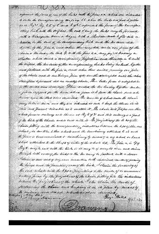
represent the form of one of the links with the pins a, a, which are intended to enter the corresponding orifices b, b, when the links are put together as in Fig 1. Fig. 5, 5, of C and b of D, represent the form of the corresponding link with the orifices. The end of any of the links may be formed with a triangular beam or tongue with a shoulder made to fit into a notch in the end of the corresponding link and the two connected together by the pins a, and when thus coupled make one piece of the chain or the ends of the link b, with the pins a, a, may project leaving a shoulder which meets a corresponding projection and shoulder in b with the orifices, the two ends of the corresponding links being held together and fastened with the pins a, and when thus united forming one piece of the chain and so each hinge piece after another are coupled until the whole succession is formed into an endless chain. This latter form is adopted in the model and drawings. When worked the two turning together make a firm support for the horse when power is to turn the chain and when travers upon the slab above described. The number of wheels into the chain may be three and they are intended as well to keep the chain in its place and prevent vibration as to sustain it. The chain as it passes over the wheels forms a railway as is shown at Fig 5 of D and this railway is a part of the links of the chain and is cast with it. The projections of the links of the chain fitting into the corresponding indentures between the lips of the end wheels give motion to the wheels and the machinery attached to it and the power is communicated to machinery by means of a cog wheel or band wheel attached to the shaft of either of the wheels 22. The piece a, in Fig 6, may be cast with the links or it may be of wrought iron and driven through both ends of the links or the two may be fastened with a screw. I claim as new and of my own invention both described modes of forming the hinge and the peculiar form of the link. I claim the forming of the end wheels with the lips or projections and the mode of communicating power by the projections of the chain fitting into the indentures between the projections of the wheels. I also claim the mode of sustaining the chain and keeping it in its place by means of the railway and small wheels as above described.
Witness my hand
Benj. Hales 945
In the presence of
[Signature]
Published accounts: journal notice
Notice in the monthly list of patents
Journal of the Franklin Institute, new ser., vol. 16 (1835), p. 287 · View the page
492. Horse power. Benjamin Wales, Hallowell, Maine,
Published accounts: journal notice
Notice in the monthly list of patents, with remarks
Journal of the Franklin Institute, new ser., vol. 17 (1836), p. 208 · View the page
50. For an improvement in the Endless Chain Horse Power; Benjamin Wales, Hallowell, Kennebec county, Maine, August 17.
Remarks. The main dependence for sustaining the slats of this horse power, is the construction of the links, or hinges, by which they are connected together; various forms of the stop hinge joints, or self-supporting arches, have been devised for the same purpose, but they are all insecure, depending too much upon the strength of each individual joint. The patentee claims, "the modes of forming the hinge, and the peculiar form of the link; the forming of the end wheels with lips and projections; the mode of communicating power by the projections of the chain fitting into the indentations between the projections of the wheels; and the mode of sustaining the chain, and keeping it in its place by means of the railway and small wheels, as described." The novelty of some of these things is more than doubtful.
About this record
- Patentee
- DATAMP
- Date
- DATAMP, USPTO records
- Invention
- DATAMP
- Listed in
- the Name and Date index of patents, DATAMP, USPTO records, Jim Shaw's X-patent list, the Journal of the Franklin Institute, Burke's List of Patents (1847)
- The sources give different dates; the date shown is the one most of them agree on.
- The Franklin Institute's journal confirms the date shown.
- Burke's 1847 Patent Office list gives the same patent.