

Drawings and documents
National Archives restored drawings: drawing
Patent Drawing for Lock Gates

National Archives, Restored Patent Drawings (Record Group 241) · Full-size scan at the National Archives · Catalog record
Show the text on the drawing Hide (17 words)
Words on the drawing as machine-read by the National Archives; not checked. Useful mainly for searching.
OIR
USPTO scan
The patent as scanned by the USPTO
-
 Page 1
-
 Page 2
-
 Page 3


U.S. Patent and Trademark Office · Google Patents
Show the transcription Hide (665 words)
Machine transcription (LightOnOCR) of the pages as scanned by the USPTO, most of them the handwritten copies made when the records were restored after the 1836 fire. Not checked; it can misread handwriting, so compare it with the scan.
Page 1.
9040X
D. WILKINSON.
CANAL LOCK GATE.
Patented Aug. 17, 1835.
THE MORRIS PETERS CO., PHOTO-LITHO., WASHINGTON, D.C.
Page 2.
9040X Aug. 17, 1835
David Wilkinson of Albany New York
Letters Patent
The Schedule referred to in these Letters Patent and making part of the same containing a description in the words of the said David Wilkinson himself of his improvement in Gates for Canal Locks.
Be it known that I David Wilkinson of Cochoes, Albany County, State of New York, have made an improvement in Gates for Canal Locks, which is described as follows.
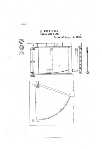
This Gate is constructed in the usual manner. The improvement consists in the mode of adjusting the friction Roller to the quadrant or circular rail any the sides to guide the chain on the capstan and ratchet or pattin the head of the capstan to prevent its being turned in a wrong direction, and the self adjusting valve gate. The friction roller is adjusted by means of a slide bar passing through the wooden bars of the Gate bearing on a sliding frame or box which contains the friction Roller. This rod is raised or lowered by a nut and screw at the top of the rod. The mode of suspension may be various to suit circumstances. The roller placed at the bottom of the capstan to guide the chain on the capstan is constructed by having a thimble to pass around the bar, the under edge of which is made in a spiral form with a tube attached to the same through which the chain passes. The top of the capstan into which the lever is inserted is made so as to contain a click or ball against which the lever may catch thus will prevent its ever being turned the wrong way. The self adjusting valve gate is constructed so as to open by the pressure of the water to effect this the gates, hung by a hinge bar or joint. There are one or more connecting rods fixed on the back side of the main gate attached to the lower edge of the valve and extending to the top of the gate which are held down by a screw at the top, or they may be held down by any other means. The valve Gate may be placed vertically as may be deemed convenient in some cases. Or the valve gate may drop by the force of the water and close upward by
Page 3.
9040X
the force of the screw or lever. Operation, When the Gate is shut it moves along the quadrant or circular rail way by the use of the chain and capstan. The lock being full of water, the catch on the screw which holds down the valve gate is detached and the screw being so graduated as to travel by the force of the water. The pressure of water opens the valve which gives motion to the screw. When the screw is sufficiently high and the ball falls into gear and holds it up. When the water is equalized in the upper and lower locks, the screw by its own weight closes the valves and the ball holds it fast till detached by hand or the ball may be dispensed with and the screw may be so graduated as to remain stationary without the assistance of the ball or latch.
The invention here claimed and desired to be secured by Letters Patent consists in the before described mode of adjusting the friction Roller in the quadrant or circular rail way, the rider to guide the chain on the capstan — the open head with balls of the capstan and the self-adjusting valve gate.
Test. Wilkins
N.Y. S. A. & Co.
Hart Smith
David Wilkinson
(1024 mds)
(Granted August 17, 1835)
Opening Mode
Published accounts: journal notice
Notice in the monthly list of patents
Journal of the Franklin Institute, new ser., vol. 16 (1835), p. 287 · View the page
468. Gates for canal locks.-David Wilkinson, Cahoes, New York,
Published accounts: journal notice
Notice in the monthly list of patents, with remarks
Journal of the Franklin Institute, new ser., vol. 17 (1836), p. 201 · View the page
The object in view, and the general means of attaining it, appear to be similar to those of Mr. Burr, in the patent numbered 31, for the last month, (July.) 27. For Gates for Canal Locks; David Wilkinson, Cohoes, Albany county, New York, August 17.
Remarks. There is a good general drawing of the apparatus patented, but the description and claim lend little or no aid in making known the views of the patentee. The latter is as follows: "The invention claimed consists in the before described mode of adjusting the friction roller, for the quadrant, or circular rail ways; the rider to guide the chain on the capstan; the open head with palls of the capstan, and the self-adjusting valve gate."
DATAMP: illustration
Illustrations from DATAMP


DATAMP (Directory of American Tool and Machinery Patents), via the Internet Archive · Archived DATAMP page
About this record
- Patentee
- DATAMP
- Date
- DATAMP, USPTO records, Burke's List of Patents (1847)
- Invention
- DATAMP
- Listed in
- the Name and Date index of patents, DATAMP, USPTO records, Jim Shaw's X-patent list, the Journal of the Franklin Institute, Burke's List of Patents (1847)
- The sources give different dates; the date shown is the one most of them agree on.
- The National Archives' catalog gives the name differently.
- The Franklin Institute's journal confirms the date shown.
- Burke's 1847 Patent Office list gives the same patent.