

Drawings and documents
National Archives restored drawings: drawing
Henry Hunsicker and Joel Krauss' Patent Drawing for a Brick Press

National Archives, Restored Patent Drawings (Record Group 241) · Full-size scan at the National Archives · Catalog record
Show the text on the drawing Hide (51 words)
Words on the drawing as machine-read by the National Archives; not checked. Useful mainly for searching.
25. / Class / 25 / Brick / Prome Box Mold; Stationary. / DIV. 15 / Singla Surfuce, / A2. / TIS U BRICK PRESS. TOEI Ik / CLASSICICATIONS / Pabented 20th Aug! 1835. / DIVISION: / 9047 + / Fig. 1. / M. / Is / y. / IV. / B. / B. / N. / 0. / ts. / AS / Fig. 2. / N. / D. / b13.
USPTO scan
The patent as scanned by the USPTO
-
 Page 1
-
 Page 2
-
 Page 3
-
 Page 4


U.S. Patent and Trademark Office · Google Patents
Show the transcription Hide (1,093 words)
Machine transcription (LightOnOCR) of the pages as scanned by the USPTO, most of them the handwritten copies made when the records were restored after the 1836 fire. Not checked; it can misread handwriting, so compare it with the scan.
Page 1.
9047X
PATENTED AUG. 20, 1835.
H. HUNSICKER & J. KRAUSS.
BRICK PRESS.
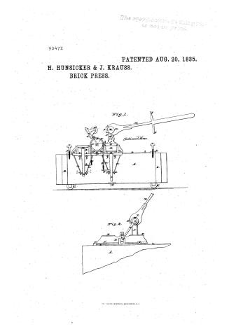
Fig. 1.
Sectional View.
Fig. 2.
THE MORRIS PETERS CO., WASHINGTON, D.C.
Page 2.
9047x Aug. 20, 1835 297.
Henry Hounickow and Joel Krauss, of Northampton Borough, Penn.
Letters Patent
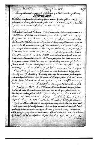
The Specification referred to in these Letters Patent and making part of the same containing a description in the words of the said Henry Hounickow and Joel Krauss themselves of their improvement in a machine for pressing and finishing Briks.
To all to whom these presents shall come. We it known that We Henry Hounickow and Joel Krauss, of the Borough of Northampton in the County of Lehigh and State of Pennsylvania have invented a new and useful machine for pressing and finishing Briks and that the following is a full and exact description of the same as invented by us. In the annexed drawing fig 1 is a vertical longitudinal section of the machine through the centre at shows one of the side pieces of which there are two, about 4 feet long 18 inches broad and placed about 10 inches inside apart. They constitute the foundation of the machine. have crofts ties at B.B. and are placed upon braces which C.C. do as to render the machine portable. D.D are a pair of cast iron briks moulds cast in one piece the sides E which connects them together being cast with a projection or flange E' on the inner side that projects internally over the bottom edge of the moulds & externally from a shoulder that fits on the tops of the two iron ways or bars E', secured on the tops of the side pieces on which the moulds are made to slide so as to bring them alternately under the operations of the pressing lever herea for mentioned, for the purpose of diminishing the friction to stop the moulds at the proper points of the sail. small friction rollers i i are let into the bottom of the moulds on each side, which drop into the depressions or notches b.b. so that the moulds may not slide on the rails while the briks is pressing. G.G. represent the covers of the moulds each having a follow C, that covers the mould a short distance, and on the top a friction roller d that bears on a strong pin or shaft e, passing through bearing f cast solid with the cover, which roller which secures the pressure from the pressing lever. j is a centre shaft which bears in suitable boxes placed on the middle of the top edge of the connecting sides of the moulds E, h.h. are two fixed arms of which there are two to each mould cover, which proceed from said shaft making an angle of about 120° with each other and are secured to the tops of the covers by screws or rivets. The object of which arrangement is to cause either cover to rise when the opposite one is depressed by the lever. H.H. are the pistons, the feet I.I. of which pass through the guides
C.C.
Page 3.
cured to the bottom of the moulds by brass blocks m, m, and screws and nuts n, n, by which they can be regulated. a rectangular strut or arm p, proceeds from each piston foot to which is connected a chain that passes over a fixed pulley I, in the centre shaft. The effect of which arrangement is that these pistons will rise or fall as their respective columns are raised or depressed. The length of the chains q is such that the piston is not supported directly whilst the bricks is pressing but bears with its under side on the adjusting screws r, r, passed up through the flange E, a screw or pin w being inserted in the top of the pulley I to prevent the chain from slipping. K represents the pressing lever which is of wrought iron 3 or 4 feet long but may be of a length proportionable to the required pressure. It is attached to a double eccentric cam L cast with a strong shaft M that bears in appropriate boxes S, S, secured to the tops of substantial iron uprights N, let into and screwed to the outsides of the side pieces and which for greater firmness are brunched and screwed near the upper edges of said pieces. From one end of the shaft M depends as seen in fig 2 a straight arm O with a friction roller T in the end of it that works in a notch X formed by 2 cogs cast solid on the outside of the connecting portion P, of the moulds. The office of which is to slide the moulds back and forth by the motion of the lever bringing them alternately under its pressure. To meet the pressure of the lever at the proper or useful point a crock bar P is screwed to the top of the side pieces A, at each end of the machine having a long screw v, in the centre with a broad head which may be elevated or depressed. Two stops y, y, being all attached to the lever the ends of which strike on the head of the screw v, and check the further descent of the lever.
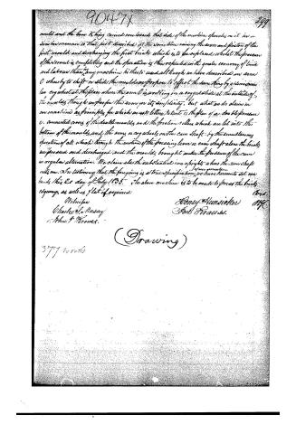
Operation. The bricks being moulded and prepared for pressing in the common way, a brick is placed in the piston of the open mould. The lever R is then drawn towards that mould and by the operation of the arm O the mould and brick is brought under the cam shaft M, by the progressive joint operation of the cam L, and arm O, the cover of the mould containing the brick having been closed, and its piston depressed so as to bear on the screw r, r, whilst the cover of the opposite mould by the same operation has been raised and its piston elevated on the lever R, being still further depressed the arm O disengages immediately from the notch X, leaving the moulds at rest and the cam common to press on the friction roller T, and continue to operate more and more powerfully until the stop y strikes the head of the screw v, and the pressure is finished. A second brick is now placed in the opposite
Published accounts: journal notice
Notice in the monthly list of patents
Journal of the Franklin Institute, new ser., vol. 16 (1835), p. 287 · View the page
505. Steam boilers. Hunsicker and Krauss, Northampton, Penn.
Published accounts: journal notice
Notice in the monthly list of patents, with remarks
Journal of the Franklin Institute, new ser., vol. 17 (1836), p. 211 · View the page
Were it not the case that floats, rods sliding in stuffing boxes, supply pumps, and other apparatus usually combined and connected in self-regulating and self-feeding contrivances, added to steam engines and their boilers, are each liable to derangement from causes which cannot be rendered self-regulating, we should expect much from the apparatus described, which is ingeniously imagined, and looks well upon paper; but we are admonished, by some knowledge of practical results, not to trust implicitly to fair promises, and specious appearances, especially where complicated machinery, and powers of difficult management and control, are concerned. 63, For a Brick Press; Henry Hunsicker, and Joel Krauss, Northampton, Lehigh county, Pennsylvania, August 20.
Remarks. This brick press possesses considerable originality, and is sufficiently well described. It contains two moulds, which are operated upon by the same lever, the moulds being upon a sort of railway, upon which they pass alternately under the lever. The moulds are of cast-iron, and their bottoms constitute movable pistons, which rise and deliver the brick at the top by the same movement which carries the moulds under the pressing lever. Each mould has its own follower, which rises, and closes on it, by the general shifting motion, all which is distinctly shown in the drawing. Theclaims made refer to the particular construction of the respective parts, for producing the action required.
DATAMP: illustration
Illustrations from DATAMP


DATAMP (Directory of American Tool and Machinery Patents), via the Internet Archive · Archived DATAMP page
About this record
- Patentee
- DATAMP
- Date
- DATAMP, USPTO records
- Invention
- DATAMP
- Listed in
- the Name and Date index of patents, DATAMP, USPTO records, Jim Shaw's X-patent list, the Journal of the Franklin Institute
- The sources give different dates; the date shown is the one most of them agree on.
- The Franklin Institute's journal confirms the date shown.