

Drawings and documents
National Archives restored drawings: drawing
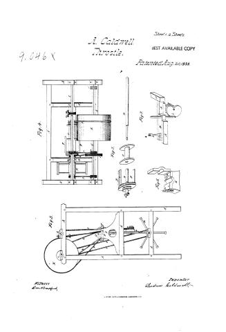
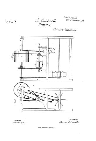
Andrew Caldwell's Patent Drawing for a Hemp and Flax Spinning Machine


National Archives, Restored Patent Drawings (Record Group 241) · Full-size scan at the National Archives · Catalog record
Show the text on the drawing Hide (394 words)
Words on the drawing as machine-read by the National Archives; not checked. Useful mainly for searching.
Sheet 1. Restoned Nov 13 - 1844. / Striceing -Jet / 118. SPINNING. / 118, SPINNING / 830 allowicd / [142] / [142] Hemp Flax &Hair / method / Shut 1st / Pr.so - / ANDREW CALDWELL's / classinication / 904lat / PIVISION. / HEMP AND FLAX SPINNING MACHINE. / Patented: 20th August, 1835 / Frig: 1. / Kig:2. / 3. / Jack / County, of Stayer the, State afor Kentucky, for. / On this fifth day. of November, 1844, before the subscriber, a purtin of the peace personally / appeared / dated the twentieth day of August, 1835, and annexed drawinguare, as he verily believes, true delineation / ed "mode of spinning hemp and flase by machineryiton which letters patent of the United States weregran / Andrew baldwell, of Lexington, Secis in the state of (Kentucky, and made solemn oath, that he is the inventor /animpton ted to him, / of the invention describedin the said letters patent. / Andrew baldwell / now / Drawn at Benne is Patent. Agency office, / subsinford of sworn to before m a pres two of the Pear for the family / Washington, D.b. / State foresand, this Just November 1844. / M.P.
Sheet 2. 118. SPINNING. / [142] / Throstics & Caps. Andrea F Sheet 1. / theatet / Hemp 8 Collon spinner and Smister / Sutented aug 20. 1835. / Fig: 1. / Gig h / Geib.delt / From Benne's Patent. Agency Office / Washington Dic.
Sheet 3. That? / A CALDWELL's / SPINNING MACHINE E / tlassification / 9046 / DIVISION. / Patented: 20th Aug. 1835. / References. / Fig: 1. Front Elevation. / 11 / 2. side do / 11. / 3. Rear do / " 4. Top - plan / 4. / 5. Represents the collared coupled spindle. / 11 6. / the spring stand. / " of / 11 / the heart, slide, Sc. / 1. Frame. / g Propelling pulley / B. Spindle. / s Pulley / Vig: / C. Spool. / t. Band / D. Pivot stand / u Heart-fully) / Es. Spring stand. / v. Fork. / F. Flyers. / w. Reel shift. / G. Drum shuft. / H. Reel. / B. The boxing of the / C/2 / I. Second shaft. / lower story, and part / K. Travers. drum. / of the upper strong floor, / Is. Heart. / are supposed to bere / M. Slide. / moved in these draw. / a. bollar. / ings. / b. Boxes. / C. Spring / d. batch. / e Flutes. / gig:5. / f smallfully / Fig: 6. / 9 Band / Turning the Keeler / h. Keel pulley / darge pulley. / Communicating / motion / K. Band / to the flyers. / 1. Double grooved, fulley, / m. small pulley, / n. Band / giving motion / a. secd shaft pulley, / to the sect Shaft. / p. Band / Drawn at Benne's Patent Agency Office, / 9 Doublegroout, pulley / Drum to spool. / motion from / Communicating / Andrew ba Idwell having ton Kig / 5th Now 1844
Sheet 4. Figs / Sheet 2. / Fry 4. / Seif deld / From Benne's Talentolyin / Washing
USPTO scan
The patent as scanned by the USPTO
-
 Page 1
-
 Page 2
-
 Page 3
-
 Page 4
-
 Page 5
-
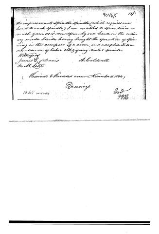 Page 6


U.S. Patent and Trademark Office · Google Patents
Show the transcription Hide (1,165 words)
Machine transcription (LightOnOCR) of the pages as scanned by the USPTO, most of them the handwritten copies made when the records were restored after the 1836 fire. Not checked; it can misread handwriting, so compare it with the scan.
Page 1.
9,046 X
Sheet 1 of 2 Sheets.
A. Caldwell.
Throttle.
BEST AVAILABLE COPY
Patented Aug. 20, 1835.

Witness
Dan Bradford
Inventor
Andrew Caldwell
PETERS, PHOTO-LITHOGRAPHER, WASHINGTON. D.C.
Page 2.
A. Caldwell.
Throttle.
Patented Aug. 20, 1835.
Sheet 2. 2 Sheets.
BEST AVAILABLE COPY
Witness
Wm Bradford.
Inventor
Andrew Caldwell
Page 3.
8-20-1835
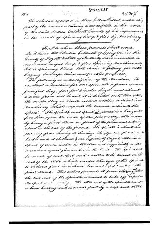
The Schedule referred to in these Letters Patent, and making part of the same containing a description in the words of the said Andrew Caldwell himself of his improvement in the mode of spinning hemp & flax by machinery.
To all to whom these presents shall come,
Be it known that I Andrew Caldwell of Lexington in the County of Fayette & State of Kentucky have invented a new and useful hemp & flax spinning machine adapted to spinning thread both chain & filling for cotton baling bail rope twine and for other purposes.
The following is a description of the machine: To construct a machine for one spindle a frame is made four feet long, four feet 8 inches high and about 2 wide from out to out, it is divided into two stories, the under story is braced in and within which is the machinery which imparts the traverse action to the spool. The spindle and spool is placed in a horizontal position upon the cover of the first story, this is done by having a pivot stand in front of the frame and a spring stand in the rear of the frame. The spindle is about two feet long from bearing to bearing. The flyers are fluted, and the back to conduct the thread & are sufficiently large to take in a spool of seven inches in the clear and sufficiently wide to receive a spool five inches in the head. The spindle to be made of cast steel and a collar to be turned on the end of the tube which causes the eye of the spindle to be held fast in a brass box and cap placed on the pivot stand. This collar prevents it from slipping when the rear end of the spindle is raised to take off or put on the spool or when racing. The other end of the spindle runs in a brass bearing and is made fast by a cap and steel
Page 4.
Spring, by touching the spring the cup flies up, and the end of the spindle can be raised for the purpose of putting on or taking off the spool, while the eye of the spindle by means of the collar aforesaid, is held fast in the first stand in front. The general form of the spindle is similar to the one in common use. The collar upon the tube end is claimed by me, also the flutes upon the flyers, together with the steel spring which fastens the caps on the rear end of the spindle as new and useful improvements. The spring above mentioned gives great facility in putting on & taking off the spool. On the top of the frame are placed two iron shafts, one immediately across the frame over the spindle & the other in an oblique direction to the right as you stand in front, on the shaft last referred to are placed several pulleys and a traversed drum as described in the Drawings hereto attached as part of this specification. The small pulley on the end of the shaft drives a band which turns the reel that receives the yarn from the spool. By this means any quantity of yarn may be thrown upon a large spool and the spool from whence it is taken be ready for use again.
The reel is placed in front of the lower story. The next is a large pulley which drives a band attached to the pulley fastened on the spindle in front of the flyers. This pulley on the flyer has two grooves, one for giving the twist for chain and the other for giving the twist for filing thread. The next is a very small pulley that drives a band and gives motion to the second shaft fixed over the spindle. The next is a drum about one foot in length & sixteen inches in diameter, this drum I call a traverse drum and on which a round band is driven, attached to the outer end of the spool, the band
Page 5.
186. 9046X
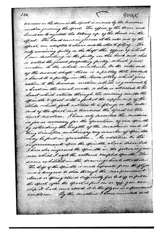
transverses on the drum or the spool is moved by the traverse motion governing the spool. The office of this drum and band are to regulate the taking up of the thread on the spool. The band runs in grooves at the outer end of the spool, one adapted to chain and the other to filing. The only remaining pulley on the shaft the office of which I am describing, is the pulley on the back end which is called the geared propelling pulley, which gives motion to the whole machine. On the outer end of the second shaft, there is a pulley that conducts a band to a pulley in the lower story which gives action to the traverse motion which is governed by a heart in the usual mode. A slide is attached to the heart which extends through the covering under the spindle & spool with a fork at the upper end of the slide which fork catches to a flange on the outer end of the spool and traverses the spool as the heart revolves. I have only described the machine so far as necessary for the operation of one spindle by extending the length of the machine and adding similar machinery any number of spindles may be put in operation. In addition to the improvements upon the spindle above described I have also improved the spindle in the following manner, which I call the collar coupled spindle. The same exhibited in the drawings hereto attached. The shaft of the spindle is made separate from the flyer and is designed to slide through the rear permanent stand or spring stand sufficiently far to drop or put on the spool, after the spool is put on or off you can slip it back, and attach it to the flyer in a permanent condition. By the machine I have invented and
Page 6.
9046X 187
the improvements upon the Spindle (which requires one hand to each Spindle) I am enabled to spin twice as much yarn as is now spun by one hand in the ordinary mode besides having brought the operation of spinning in the compass of a room, and adapted it to a new source of labor old & young male & female.
Witnessed
James C. Davis A. Caldwell
Jno M. Lear
(Received & Recorded anew November 11, 1844)
Drawings
12.45 w-45
End
J.M.L.
Published accounts: journal notice
Notice in the monthly list of patents, with remarks
Journal of the Franklin Institute, new ser., vol. 17 (1836), p. 209 · View the page
57. For machinery for Spinning Hemp and Flax; Andrew Caldwell, Lexington, Fayette county, Kentucky, August 20.
Remarks. The patentee says that, "by the machine I have invented, and the improvements upon the spindle, (which requires one hand to each spindle,) I am enabled to spin twice as much yarn as is now spun by one hand in the 22* ordinary mode, besides having brought the operation of spinning into the compass of a room, and adapted it to a new source of labour, old and young, male and female." He does not, however, make any distinct claim, but leaves it to be inferred, from the general description, in what his invention consists. A number of figures are given in the drawings, and we cannot afford the space which without these would be required to describe the article.
About this record
- Patentee
- the Journal of the Franklin Institute, Journal
- Date
- USPTO records, Jim Shaw's X-patent list, Burke's List of Patents (1847)
- Invention
- the Name and Date index of patents
- Listed in
- the Name and Date index of patents, USPTO records, Jim Shaw's X-patent list, the Journal of the Franklin Institute, Burke's List of Patents (1847)
- The sources give different dates; the date shown is the one most of them agree on.
- The patentee's full name comes from the Franklin Institute's journal.
- The Franklin Institute's journal confirms the date shown.
- Burke's 1847 Patent Office list gives the same patent.