

Drawings and documents
National Archives restored drawings: drawing
Alfred Jones' Patent Drawing for a Spark Arrester

National Archives, Restored Patent Drawings (Record Group 241) · Full-size scan at the National Archives · Catalog record
Show the text on the drawing Hide (75 words)
Words on the drawing as machine-read by the National Archives; not checked. Useful mainly for searching.
- BOILER FURNACED, / Spark Arrestess. / 75c / ALFRED C. JONES'S / 90.58 / DIVISION. / SPARK ARRESTER / th / Patented 27. Aug. 1b / 1835 / self / Fig. / to be to / Fig. 2. / H. / wire / H. B / GI / B. / D. / I. / H. / F 0 / C. / D. / C.1. / realisy of / 0.1 / Small holes as - / to humits country / Respond for sparkly / of shark ,So etcoms / wanders- / the botters of sogue / B. / Fig. 3.
USPTO scan
The patent as scanned by the USPTO
-
 Page 1
-
 Page 2
-
 Page 3
-
 Page 4


U.S. Patent and Trademark Office · Google Patents
Show the transcription Hide (917 words)
Machine transcription (LightOnOCR) of the pages as scanned by the USPTO, most of them the handwritten copies made when the records were restored after the 1836 fire. Not checked; it can misread handwriting, so compare it with the scan.
Page 1.
9058X
A.C. Jones,
Spark Arrester,
Patented Aug. 27, 1835.
Fig. 1
Fig. 2.
Fig. 3.
Page 2.
9658X Aug. 27, 1835
Alfred C. Jones of Portsmouth, Virginia
Letters Patent.
The schedule referred to in these Letters Patent and making part of the same containing a description in the words of the said Alfred C. Jones himself of his improvement in an instrument or apparatus for arresting the sparks proceeding from the furnaces of steam engines.
To all whom it may concern.
Be it known that I Alfred C. Jones now residing at Portsmouth in the County of Norfolk and State of Virginia have invented improvements in the apparatus for arresting the sparks which proceed from the furnaces of steam engines, and that the following is a full and exact description thereof reference being had to the drawings which accompany and make a part of this specification. Fig. 1. is a longitudinal section of the apparatus taken vertically through the chimney Fig. 2. is a perspective view representing the cap and its appurtenances complete, with the exception of the wire gauge which is to be strained over the frame, as which has been omitted in the drawing for the more perfect exhibition of the other parts. Fig. 3. is a section of the of the smoke chamber of a (locomotive engine) showing the pipe for conveying the sparks to its bottom the same letters serve to designate similar parts. A. is the smoke pipe or chimney. B. the cap or frame which is to be covered with wire gauge C. C. are receptacles for sparks and cinder. D. a funnel or opening furnished with a shutter or valve. E. which has a counterbalancing weight F. attached to it. G. G. are sliding doors H. H. H. are cross rods forming a part of the framework of the cap. I. I. hinges to admit of the cap being thrown back to prevent the gauge from closing with
Langhlin
Page 3.
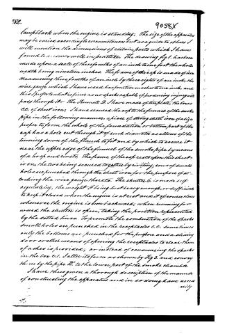
lampblack when the engine is standing; the size of the apparatus may be varied according to circumstances but as a guide to others I will mention the dimensions of certain parts which I have found to answer well in practice. The drawing fig 1. has been made upon a scale of three sixths of an inch to one foot the whole width being nineteen inches. The frame of the cap is made of iron measuring three sixths of an inch by three eights of an inch; the wire gauge which I have used has fourteen meshes to one inch, and this I prefer to what is finer as no sparks capable of producing injury will pass through it. The funnel D. I have made of tin plate, the boxes C.C. of sheet iron, I have secured the cap to the funnel of the smoke pipe in the following manner, a piece of strong sheet iron of a size proper to form the whole of the foundation or bottom part of the cap has a hole cut through it of such diameter as allows of the turning down of the flanch to fit and by which to secure it near the upper edge of the funnel of the smoke pipe by means of a hoop and rivets. The frame of the cap rests upon this sheet iron, the two being secured together by riveting; rows of small holes are punched through the sheet iron for the purpose of attaching the wire gauge thereto. The shutter E. is made self-regulating, the weight F being just heavy enough, or sufficient to keep it closed when the engine is at rest and it of course closes whenever the engine is run backward; when running forward the shutter is open, taking the position represented by the dotted lines. To promote the combustion of the sparks small holes are punched in the receptacles C.C. sometimes only the bottoms are punched for the purpose and a sliding door or other means of opening the receptacles to clear them of ashes is provided; or instead of consuming the sparks in the box C.1. I alter its form as shown by Fig 3. and convey them by the pipe H. to the lower part of the smoke chamber. I have thus given a thorough description of the manner of constructing the apparatus and in so doing have necessarily
Page 4.
Necessarily mentioned certain parts thereof of which I do not claim to be the invention, caps of several constructions covered with wire gauze having been before used for the same purpose, but I do claim as new and of my invention the open funnel marked D, in the drawing and the self-regulating shutter, or valve, placed therein, so balanced that it will be open and admit air, by the advance of the engine and also when it is at rest and these I claim in all the variations of form of which they are susceptible, whilst they are so constructed as to operate upon the same principles and produce similar effects. I also claim the conveying of the sparks by the pipe N to the bottom of the smoke chamber out of the influence of the boiler flues and the making the cap with hinges for the before-mentioned purpose.
Witnesses
J. Brooke
O. C. Guison
Alfred C. Jones
(Drawing)
Filed
Nov. 6.
Published accounts: journal notice
Notice in the monthly list of patents
Journal of the Franklin Institute, new ser., vol. 16 (1835), p. 287 · View the page
510. Arresting sparks. -Alfred C. Jones, Portsmouth, Virginia,
Published accounts: journal notice
Notice in the monthly list of patents
Journal of the Franklin Institute, new ser., vol. 17 (1836), p. 213 · View the page
68. For Arresting the Sparks from Locomotive Engines; Alfred C. Jones, Portsmouth, Norfolk county, Virginia, August 27.
About this record
- Patentee
- the Journal of the Franklin Institute, Journal
- Date
- the Name and Date index of patents, USPTO records, Jim Shaw's X-patent list
- Invention
- the Name and Date index of patents
- Listed in
- the Name and Date index of patents, USPTO records, Jim Shaw's X-patent list, the Journal of the Franklin Institute, Burke's List of Patents (1847)
- The patentee's full name comes from the Franklin Institute's journal.
- Burke's 1847 Patent Office list gives the same patent.