

Drawings and documents
National Archives restored drawings: drawing
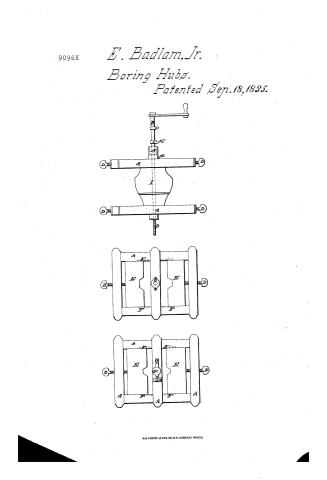
Edwards Badlam, Jr.'s Patent Drawing for a Machine for Setting Boxes

National Archives, Restored Patent Drawings (Record Group 241) · Full-size scan at the National Archives · Catalog record
Show the text on the drawing Hide (42 words)
Words on the drawing as machine-read by the National Archives; not checked. Useful mainly for searching.
144. WOOD WORKING. / 3. SPECIAL WORK MACHINERY. / [31] Boring Hubs. / EDWARD BADLAM JR / #150 / SETTING BOXES. / vertical View. / 9096-4 / Patented 18th Sept:1835. / is / To / Top Frame. / Bottom Frame. / OH / Referenees
USPTO scan
The patent as scanned by the USPTO
-
 Page 1
-
 Page 2
-
 Page 3


U.S. Patent and Trademark Office · Google Patents
Show the transcription Hide (736 words)
Machine transcription (LightOnOCR) of the pages as scanned by the USPTO, most of them the handwritten copies made when the records were restored after the 1836 fire. Not checked; it can misread handwriting, so compare it with the scan.
Page 1.
9096X
E. Badlam, Jr.
Boring Hubs.
Patented Sep. 18, 1835.

AM. PHOTO-LITHO. CO. N.Y. (OSBORNE'S PROCESS)
Page 2.
9096X Sept. 18, 1835 377.
Edward Badlam Jr. of Chester, Vermont:
Letter Patent
Their schedule referred to in these Letters Patent and making part of the same containing a description in the words of the said Edward Badlam Jr. himself, of his improvement in the Box Setter for boring out and fitting all kinds of common and pike boxes in hubs &c,
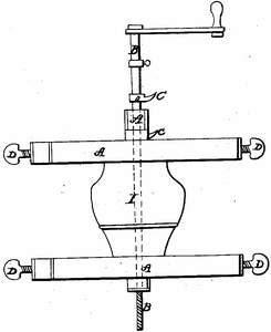
To all to whom these presents shall come: Be it known that I, Edward Badlam Jr. of Chester, in the County of Windsor, and State of Vermont, have invented a new and useful improvement in the Box Setter, for boring out and fitting all kinds of common and pike boxes in hubs &c, and that the following is a full and exact description of my said improvement. The box setter is constructed as follows viz: make two square frames with slides in which are placed dies to receive hubs of all sizes, these dies are regulated by means of screws which screw through each end of the frames and press against the back of each die. On the side of each of the frames there is a scale of inches and eights of inches for the purpose of regulating the distance of the dies from the center of each of the frames. These frames are placed one on each end of a hub and whatever may be the diameter of the hub to be operated upon the dies are so shaped as to fit it and the scale on the side of each frame will designate when the center of the hub is in the center of the frame. On the top of one of the frames there is fixed a cross piece which is raised from the surface of the frame about two inches having a hole with a metallic box to receive a shaft to be hereafter described, and on the surface of the other frame, there is also a cross piece made fast to it, in the middle of which is a metallic nut set into it and kept into its place by means of two buttons for the convenience of removing. The shaft above mentioned is made of iron, perfectly cylindrical with a crank at one end, and a screw at the other; said screw to be of less diameter than the other part of the shaft, and made to work in the nut above described. Three mortises are cut through the shaft about two or three inches apart in which are inserted cutters for setting all kinds of common or pike boxes. The set of the cutters is affected by means of thumb screws. A washer is set on to the shaft
Page 3.
3/8. 9096x
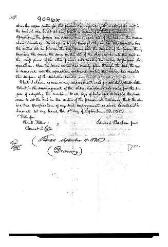
above the upper cutter for the purposes of regulating the depth of the cut in the hub, it can be set at any point by means of a thumb screw. Operation. The frames are secured one to each end of the hub, in the manner above described. The shaft is passed through the hole in the metallic box. The cutters set in between the cross pieces and the surface of the frames. Thru turning the crank the screw on the end of the shaft works into the nut on the cross piece of the other frame and enables the cutter to perform their operation. When the lower cutter has nearly gone through the hub, the nut is removed and the operation continued until the washer has reached the surface of the metallic box.
What I claim as new, as my improvement, and for which I solicit Letters Patent, is the arrangement of the slides, dies, screws, and scales, for the purpose of adapting the machine to all sizes of hubs and to enable the workmen to set the hub in the centre of the frame. In testimony that the above is a true specification of my said improvement as above described, I have hereunto set my hand this 5th day of September A.D. 1835.
Witnesses
Chas. H. Keller
Clement J. Coote
Edward Badlam junr.
(Patented September 18, 1835)
(Drawing)
[752]
Published accounts: journal notice
Notice in the monthly list of patents, with remarks
Journal of the Franklin Institute, new ser., vol. 17 (1836), p. 262 · View the page
38. For a machine for Setting Boxes in Hubs; Edward Badlam, Jr., Chester, Windsor county, Vermont, September 18.
Remarks. The hub is to be fixed on a frame, being adjusted by screws, so that it shall be properly centred. A shaft, fitted into collars, and turned by a winch, carries the cutters which are to let in the box, which cutters are made adjustable, in order to adapt them to the required size. The claim is to "the arrangement of the slides, dies, screws, and scales, for the purpose of adapting the machine to all sizes of hubs, and to enable the workman to set the hub in the centre of the frame." There are several patented machines for the same purpose, arranged in a very similar way, and possessing all the virtues of the foregoing.
DATAMP: illustration
Illustrations from DATAMP

DATAMP (Directory of American Tool and Machinery Patents), via the Internet Archive · Archived DATAMP page
About this record
- Patentee
- DATAMP
- Date
- the Name and Date index of patents, DATAMP, USPTO records
- Invention
- DATAMP
- Listed in
- the Name and Date index of patents, DATAMP, USPTO records, Jim Shaw's X-patent list, the Journal of the Franklin Institute, Burke's List of Patents (1847)
- Burke's 1847 Patent Office list gives the same patent.