

Drawings and documents
National Archives restored drawings: drawing
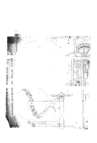
Edwards Badlam's Patent Drawing for a Cradling Machine and Grass Cutter

National Archives, Restored Patent Drawings (Record Group 241) · Full-size scan at the National Archives · Catalog record
Show the text on the drawing Hide (52 words)
Words on the drawing as machine-read by the National Archives; not checked. Useful mainly for searching.
HARY / Dr / Anomalies. / TEX ID W A IR IID. THB Al ID TA A MI. , / CLASSIPICATION / 9007.7 t / CRADLING MACHINE; AND GRASS CUTTER . / DIVISION, / Patented 18. th Sep 1835. / PS / 80 / if / B. / bo / as / 00 / 10 / P C. ( / K. / If / If
USPTO scan
The patent as scanned by the USPTO
-
 Page 1
-
 Page 2
-
 Page 3


U.S. Patent and Trademark Office · Google Patents
Show the transcription Hide (700 words)
Machine transcription (LightOnOCR) of the pages as scanned by the USPTO, most of them the handwritten copies made when the records were restored after the 1836 fire. Not checked; it can misread handwriting, so compare it with the scan.
Page 2.
$\text{Sept. 18 1835} \quad 221$
Edward Badlam Jr. of Chester, Vermont.
Letters Patent
9097X
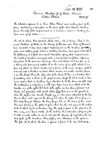
The schedule referred to in these Letters Patent and making part of the same, containing a description in the words of the said Edward Badlam Junior, himself, of his improvement in a machine called a cradling machine and grass cutter---
To all to whom these presents shall come: Be it known that I, Edward Badlam of Chester, in the County of Windsor, and State of Vermont, have invented a new and useful improvement in the machine for cutting grain and cutting grass, called a cradling machine and grass cutter. That the following is a full and exact description of my said improvement.
The cradling machine and grass cutter is constructed, as follows reference being had to the annexed drawings. Two cast wheels A.A. are put on to a strong and permanent axle tree B. on the inside of one of the wheels A, is a face cog wheel C, which meshes into a pinion D, the under surface, of which is made into a bevelled cog wheel, which meshes into another bevelled pinion E, on the shaft F. On the other end of the shaft F, there is a bevelled wheel G, meshing into a wheel on the perpendicular shaft H, which works in boxes a.a.a. and is kept in its place by a shoulder b. To the lower end of the shaft H, is attached a cross piece c, with iron loops d.d.d.d, in which work the handles e.e, of the sythes J.J. Back of the sythes are two pieces of wood X.X, which are provided with small rollers f.f.f.f. that run on the ground to raise the sythes over small knuckles g.g. are two arms attached to the handles e.e, that work against the springs h.h, above the sythes J.J. are fingers i.i, that pass through between the long fingers k.k, in the course of their revolution and discharge the grass or grain, that has been cut against the inclined rack l, which by its inclination lays the grass or grain on the ground in the same way as a hand cradle. To the axle tree B, is attached a projecting bar L, with a castor roller m, on its end, for the purpose of regulating the rise and fall of the machine when passing over elevations on the ground. The pole M, to which the team is geared, is fixed to the two hooks n.n.
Page 3.
9097X
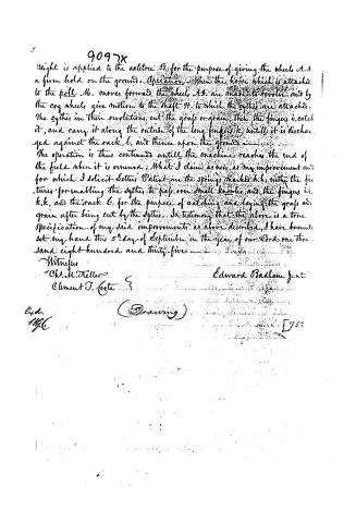
Weight is applied to the axle-tree, B, for the purpose of giving the wheels A, A, a firm hold on the ground. Operation: When the horse, which is attached to the pole, M, moves forward, the wheels, A, A, are made to revolve, and by the cog wheels, give motion to the shaft, H, to which the cythes are attached. The cythes in their revolutions cut the grass or grain; then the fingers, i, catch it, and carry it along the outside of the long fingers, k, until it is discharged against the rack, l, and thence upon the ground.
The operation is thus continued until the machine reaches the end of the field when it is reversed. What I claim as new, as my improvement and for which I solicit Letters Patent are the springs marked h, h, with the fixtures for enabling the cythes to pass over small knolls, and the fingers i, i, k, k, and the rack l, for the purpose of catching and laying the grass and grain after being cut by the cythes. In testimony that the above is a true specification of my said improvement as above described, I have hereunto set my hand this 5th day of September in the year of our Lord one thousand eight hundred and thirty-five.
Witnesses
W. M. Keller
Clement J. Coote
Edward Badlam Jr.
Exd.
11/6
(Drawing)
[752]
Published accounts: journal notice
Notice in the monthly list of patents, with remarks
Journal of the Franklin Institute, new ser., vol. 17 (1836), p. 263 · View the page
41. For a Cradling and Mowing Machine; Edward Badlam, Jr., Chester, Windsor county, Vermont, September 18.
Remarks. By means of a face cog wheel on the inside of one of the wheels upon which the machine runs, motion is given to a horizontal shaft, the opposite end of which gears into a bevilled pinion on a vertical shaft, which sustains scythes, revolving horizontally. Small wheels on the underside of the fixtures of these scythes, run upon the ground, and serve to raise them over knolls, whilst springs above them keep them in their places; the grass, or grain, is received upon fingers, which conduct to a rack. The claim is to "the springs, with the fixtures for enabling the scythes to pass over small knolls; the fingers and the rack, for the purpose of catching and laying the grass and grain, after being cut by the scythes."
About this record
- Patentee
- DATAMP
- Date
- the Name and Date index of patents, DATAMP, USPTO records
- Invention
- DATAMP
- Listed in
- the Name and Date index of patents, DATAMP, USPTO records, Jim Shaw's X-patent list, the Journal of the Franklin Institute, Burke's List of Patents (1847)
- Burke's 1847 Patent Office list gives the same patent.