

Drawings and documents
National Archives restored drawings: drawing
George Pack's Patent Drawing for a Stave Cutting Machine

National Archives, Restored Patent Drawings (Record Group 241) · Full-size scan at the National Archives · Catalog record
Show the text on the drawing Hide (101 words)
Words on the drawing as machine-read by the National Archives; not checked. Useful mainly for searching.
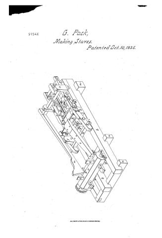
144. WOOD WORKING MACHINES. / Slicers, Rotary & Oscillating. / Mary ed / ASSIFICATION / 9154-4 / DIVISION / stare culting Machine / Patented: 10 Oct: 1835 / References. / a brops sills / b Frame timbers. / c. Revolving shaft / d. arms or cogs / e bag wheel / f Uprights / g small shaft / h Knife frame / i hever / Knife / m Feeding carriage / is / From plate / Moveable jaw / Screw rod / Hand / d. Upright / Patent Office. 28th Sept 1639. / t Morizontal asle / Long lever / Made under the direction of the Commitioner of Patents / in conformity with act of March 183% / Comm. of Patents
USPTO scan
The patent as scanned by the USPTO
-
 Page 1
-
 Page 2
-
 Page 3
-
 Page 4


U.S. Patent and Trademark Office · Google Patents
Show the transcription Hide (1,120 words)
Machine transcription (LightOnOCR) of the pages as scanned by the USPTO, most of them the handwritten copies made when the records were restored after the 1836 fire. Not checked; it can misread handwriting, so compare it with the scan.
Page 1.
9154X
G. Pack,
Making Stares.
Patented Oct. 10, 1835.
AM. PHOTO-LITHO. CO. N.Y. (OSBORNE'S PROCESS)
Page 2.
George Pache
Letters Patent
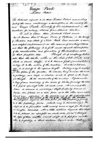
The Schedule referred to in these Letters Patent and making part of the same containing a description in the words of the said George Pache himself of his improvement in the machine for cutting staves from steam timber.
We all to whom these presents shall come.
Be it known that I George Pache of Sullivan in the County of Madison and State of New York have invented a new and useful improvement in the manner of making staves and that the following is a full and exact description of the construction and operation of the machine used for that purpose (viz). Though it is necessary to premise that the timber either in the shape of bolt plank, round block or sawed stuff, is to be steamed first previous to presenting it to the action of the machine. And this is best done after it is cut off to the required length. Boiling may be employed instead at the option of the operator, the intention being to render the wood so yielding and tough or elastic as not to split as the knife goes through. In the construction of the machine I first make a long frame consisting of two pieces of timber forming the sides to be fixed upon cross sills at each end. At one end of this frame is secured a revolving shaft properly secured in boxes, one placed on a side piece and the other on an additional one attached to the opposite end of the cross sills, which a cog wheel is here added to the end of the shaft for the purpose, there project beyond the side piece for that purpose, of gearing in to the propelling power (which may be discretionary). The shaft is to be furnished with rows of arms or cogs for the purposes hereafter described. At a little distance beyond this shaft is to be placed an upright on each side piece and through the tops of these another small shaft is to pass from one to the other & projecting a short distance beyond each, the projections form
Page 3.
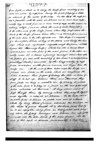
form pivots on which is to swing the knife frame consisting of two sides connected by cross pieces having the pivots playing a little in advance of the centre of the sides. On the top of the cross pieces & parallel with the sides, are placed one or more levers sufficiently long to reach from one or more rows of eggs on the main revolving shaft (and on which the ends of said levers rest) to the other end of the knife frame where they press upon the back of the knife placed below them & extended from one end of the side piece to the other opposite one. This knife consists of a broad flat blade as long as the staves and having the broad edge sharp and extended edge-wise across the frame. A little beyond this balancing knife (which has also a broad block extended from one side piece of the main frame to the other actually under it) is placed a feeding carriage some what after the fashion of a saw mill consisting of two sides & a middle piece (something shorter) connected together horizontally by cross pieces so as to form another frame narrower and longer than the knife one. At the ends of these sides next the knife are placed iron plates on the inside which are roughened the better to answer their purpose of holding the bolts or piece of stuff to be cut up. Between them and the ends they form jaws, one being a movable one, by placing it outside of the side piece & to play as a joint on the end of the cross piece situated at that end. A long screw rod is to pass through them by turning which they may be tightened together or released at pleasure. On the centre short middle piece is placed a rack and one at a hand which by being thrust forward advances the carriage on the slide & groove beneath it & this hand joins loosely on to an upright rising from an horizontal axle playing above the feeding carriage and between two uprights secured into the side pieces of the main frame. At the end of this axle is secured permanently a long lever which
Page 4.
9154X
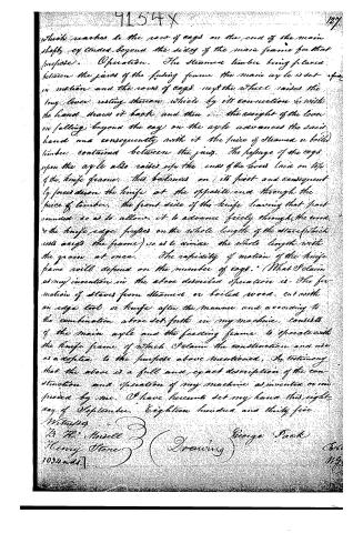
which reaches to the row of cogs on the end of the main shaft, extended beyond the sides of the main frame for that purpose. Operation. The steamed timber being placed between the jaws of the feeding frame the main axle is set in motion and the rows of cogs on the wheel raises the long lever resting thereon which by its connection with the hand draws it back and then the weight of the lever on falling beyond the cog on the axle advances the said hand and consequently with it the piece of steamed or boiled timber contained between the jaws. The passage of the cogs upon the axle also raises up the ends of the lever laid on top of the knife frame: this balances on its pivot and consequently forces down the knife at the opposite end through the piece of timber, the front side of the knife leaving that part rounded so as to allow it to advance freely through the wood, & the knife edge grinds on the whole length of the stave (which rests across the frame) so as to divide the whole length with the grain at once. The rapidity of motion of the knife frame will depend on the number of cogs. (What I claim as my invention in the above described operation is: The formation of staves from steamed or boiled wood, cut with an edge tool or knife after the manner and according to the combination above set forth in my machine, consists of the main axle and the feeding frame to operate with the knife frame of which I claim the construction and use as a matter to the purpose above mentioned. In testimony that the above is a full and exact description of the construction and operation of my machine as invented or improved by me, I have hereunto set my hand this eight day of September, eighteen hundred and thirty five.
Witnesses
B. H. Moselle
Henry Stone
George Pack
(Drawing)
1034nds.
127
Published accounts: journal notice
Notice in the monthly list of patents
Journal of the Franklin Institute, new ser., vol. 17 (1836), p. 70 · View the page
611. Staves, cutting.--George Pack, Sullivan, New York,
Published accounts: journal notice
Notice in the monthly list of patents, with remarks
Journal of the Franklin Institute, new ser., vol. 17 (1836), p. 331 · View the page
23. For a Machine for Making Staves; George Pack, Sullivan, Madison county, New York, October 10.
Remarks. This machine, it appears, is intended only for the jointing of staves, after they have been otherwise prepared, which jointing is to be effected by a long knife, reaching from end to end. The staves are to be first boiled, or steamed, to render them tender; they are then placed between jaws, embracing their ends, and advanced under the knife by a horizontal sliding table, moved by a rack and feed hand; the knife is to be forced down by lifters, operating under one end of a lever, to which it is attached.
About this record
- Patentee
- Jim Shaw's X-patent list
- Date
- the Name and Date index of patents, USPTO records, Jim Shaw's X-patent list
- Invention
- the Name and Date index of patents
- Listed in
- the Name and Date index of patents, USPTO records, Jim Shaw's X-patent list, the Journal of the Franklin Institute, Burke's List of Patents (1847)
- The residence comes from the Franklin Institute's journal.
- Burke's 1847 Patent Office list gives the same patent.