

Drawings and documents
National Archives restored drawings: drawing
C.W. Cleaveland's Patent Drawing for a Self-Adapting Rail Road Car


National Archives, Restored Patent Drawings (Record Group 241) · Full-size scan at the National Archives · Catalog record
Show the text on the drawing Hide (130 words)
Words on the drawing as machine-read by the National Archives; not checked. Useful mainly for searching.
Sheet 1. 60 / as / If / of / oyony
Sheet 2. Trucks / our success / Jennifuil / asles sectoral / long R.R. bois / 1405. Railway Rolling Stock, / Trucks, Four Wheel, / Joh / Curve Adjustors, / Axles, Sectional. / 9161-t / DIVISION. / Hig. 2. / aid Section of the circular revolving / box; sheming its diameter and thick / and sonore in mhich the outer / journaz of the axte corolves. / Iiz.3. Sideview of the Centre box. / HL / -4.A. upper Plate / B.B. under Plate. / C.C. Thimbles. / D.D. vibrating box. / e.e. Hole in - do / f.f. Axis of Pirot lever. / Fig: 4 / g.g. Pirol Jiever. / 72.21. Centre Perch. / OR / Axles / B. Piroe Lever. / C.C. Axis of Pirol Zerez / Ind view of Centre box / D.D. Tibrating boxes.
USPTO scan
The patent as scanned by the USPTO
-
 Page 1
-
 Page 2
-
 Page 3
-
 Page 4


U.S. Patent and Trademark Office · Google Patents
Show the transcription Hide (1,224 words)
Machine transcription (LightOnOCR) of the pages as scanned by the USPTO, most of them the handwritten copies made when the records were restored after the 1836 fire. Not checked; it can misread handwriting, so compare it with the scan.
Page 1.
9161X
G. W. CLEAVELAND.
Car Truck.
Patented Oct. 14, 1835.
Fig. 1
Fig. 2
Fig. 3
Fig. 4
N. PETERS, PHOTO-LITHOGRAPHER, WASHINGTON. D. C.
Page 2.
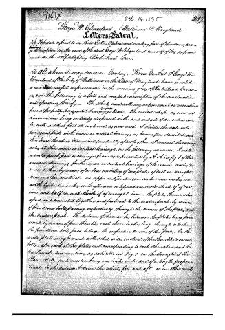
George W. Cleaveland, Baltimore, Maryland
Letters Patent.
The Schedule referred to in their Letters Patent and making part of this same conveyance, a description in the words of the said George W. Cleaveland himself of his improvement in the self-adapting Rail Road Car.
To all whom it may concern. Greeting. Know Ye that I George W. Cleaveland of the City of Baltimore in the State of Maryland have invented a new and useful improvement in the running gear of Rail Road Carriages and the following is a full and complete description of the construction and operation thereof. The wheels used with my improvement or invention have a perfectly horizontal bearing surface. The conical shape as now in common use being entirely dispensed with and instead of an entire axle with a wheel fast at each end as now used, I divide the axle into two equal parts with inner or central bearings as herein after described and thus leave the wheels to turn independently of each other. I connect the same axles at their inner or central bearings, in the following manner. I make a centre perch part or carriage frame as represented by A A in Fig 1 of this annexed drawings for the inner or central bearings of the same axles & connect them by means of a box consisting of two plates of cast or wrought iron or other material, an upper and under one, each nine inches in width by two inches in length more or less and one inch thick if of cast iron and half an inch thick if of wrought iron. The plates, three inches apart and connected together and fastened to the centre perch by means of four screw bolts passing respectively through the corners of the plates and the centre perch. The distance of three inches between the plates being preserved by means of four thimbles each three inches long, through which the four screw bolts pass, between the respective corners of the plates. Or the under plate may be made with solid sides instead of the thimbles & screw bolts. In each of the plates and corresponding to each other above and below I make two notches as exhibited in Fig 1. on the draught of the Plate B B, each notch being one inch wide and of a length proportionate to the distance between the wheels fore and aft, or in other words
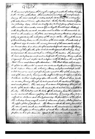
Page 3.
to the amount of vibration that may be necessary to enable this wheel to conform to the direction of the rails. These motions are in shape the arc of a circle, having the semi-axle for a radius and for its centre the centre of the revolving box of the outer journal bearing as described. In this box thus constructed, place two vibrating boxes which are simply two circular pieces of cast iron or other metal. These boxes measure six inches in length, breadth and thickness, with two flanges on each one above and one below on the same side to work in the notches in the plates, and corresponding notches in shape and acting as guides in the vibrations of the semi-axles. Through the centre of these vibrating boxes, in the direction of the semi-axles, I make holes of sufficient size to receive the inner journals of the semi-axles which are turned down to a diameter of one and a half inches more or less, leaving shoulders of three-fourths of an inch to work against the vibrating boxes and prevent the semi-axles from sliding to the centres. The journals of the semi-axles pass an inch and a half into the vibrating boxes or rather if required but not so far as to interfere with the balls on the ends of the Pivot Lever hereinafter described. The Pivot Lever which may be of iron or other metal is made six inches in length more or less according to the distance between the vibrating boxes and of an oval shape with a ball turned on each end of a diameter equal to that of the inner journals of the semi-axles, leaving notches sufficiently small to permit the balls to vibrate without infringing upon the notches. The pivot lever works on an axis passing through its centre and into the centres of the upper and under plates. This axis may be a screw bolt passing through the centre of the centre box and the centre fork and serving as a fastening thereby. The balls pass into the holes in the vibrating boxes thus their diametric and work therein regulating the vibration by causing them to correspond in distance and thereby preventing the parallelism of the wheels. The vibrating boxes may be made to slide over friction rollers fixed in the upper plate if preferred. The boxes in which the outer journals of the semi-axles work are constructed in the usual manner except that in the upper or bearing plate of each box I make a circular depression or bed of a diameter equal to the circular revolving box and
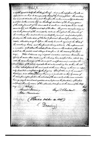
Page 4.
a depth equal to half the thickness thereof. And in the cast piece I make a depression or bed to correspond to that of the bearing plate. The revolving box is made circular four and three-fourths inches more or less in diameter and two inches more or less in thickness exclusive of the bearing groove of the outer journal of the semi-axle to work in, and is sunk one inch more or less into the plate and cast of the Box. The groove corresponding in size to the journal of the semi-axles extends throughout the diameter of the revolving box and embraces one half the journal, and instead of depending on the outer side of the box to prevent the axle from sliding outwards, shoulders may be left on the axles to work against the sides of the revolving boxes, and thus prevent sliding outwards. This improvement or invention will allow the wheels of a car to run on the outside of the rails as well as the inside, and always to conform to the course of the Rail way. What I claim as my original invention and never known to me before is the centre Box containing the vibrating box, and pivot lever which connect the inner bearings of the semi-axle and preserve and maintain the parallelism of the wheels, and also the circular revolving box within the outer Box which permits the semi-axle at the inner bearing as the same are respectively described and explained by the foregoing Specification and the annexed drawings, in no whatever manner they may be constructed so that by means of the same principles of action the vibration of the semi-axles at their inner or centre bearings may be caused and regulated so as to preserve the parallelism of the wheels and permit them by means of their flanges to conform to the course of the Rail way.
Witnesses:
Samuel Manning
George H. Cleveland
John Penniman
1321035 (Patented October 14, 1855)
(Drawing)
Published accounts: journal notice
Notice in the monthly list of patents, with remarks
Journal of the Franklin Institute, new ser., vol. 17 (1836), p. 334 · View the page
34. For Running Gears for Rail Roads; George W. Cleveland, city of Baltimore, October 14.
Remarks. The object of this invention is to admit of the vibration of the axles of the wheels, in such a manner as that the latter shall always conform themselves to the curvature of the road. Each wheel has its distinct axis, there being a centre pivot to sustain the end of each, which inner ends revolve in a vibrating bar, allowing the axis to vibrate horizontally. The outer ends of the axles run in bearings which conform themselves to the motion of the inner ends of the axles. The tread of the wheels is to be perfectly flat, without any cone, or rise, towards the flanches, and it appears that the wheels are to conform themselves to the direction of the rail by the action of the flanches upon them; a very short time will, we apprehend; demonstrate the worthlessness of this plan. The particular construction of the parts require the drawing for a proper explanation of them. Upon these the claims are founded, and are also made to any other way in which "they may be constructed, so that by means of the same principles of action, the vibration of the semi-axles at their inner bearings, may be caused and regulated, so as to preserve the parallelism of the wheels, and permit them, by means of their flanches, to conform to the course of the rail-way."
About this record
- Patentee
- Jim Shaw's X-patent list
- Date
- the Name and Date index of patents, USPTO records, Jim Shaw's X-patent list
- Invention
- the Name and Date index of patents
- Listed in
- the Name and Date index of patents, USPTO records, Jim Shaw's X-patent list, the Journal of the Franklin Institute, Burke's List of Patents (1847)
- The Franklin Institute's journal spells the name differently.
- Burke's 1847 Patent Office list gives the same patent.