

Drawings and documents
National Archives restored drawings: drawing
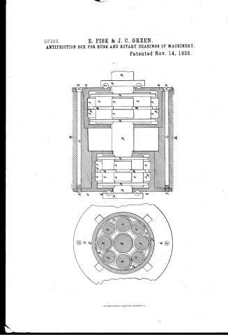
E. Fisk and J.C. Green's Patent Drawing for an Anti-Friction Box for Hubs and Rotary Bearings of Machinery

National Archives, Restored Patent Drawings (Record Group 241) · Full-size scan at the National Archives · Catalog record
Show the text on the drawing Hide (97 words)
Words on the drawing as machine-read by the National Archives; not checked. Useful mainly for searching.
ation / eap lour.-Boxes,Pulley Bhafting, / Roller Bearings, / Pimary Roller / Oylinder, / 8 Inlo@b O GREEN / Circular Beries. / B. / Axleoor shift / C Rollers / Anti Friction Box for Hills,8 rotary bearings of Machinery / D. collar / Pritenting 1835 / to transues on secondary morning ingreases inprimary Rollers / to Hoar 11 / CLASSICICATION / 70221 / G circular plate / 9239x / DIVISION / 9239X / IC / 7° / H Grooved Collar on axle / I. Ball moving 272 / Patent offer / Plate receiving Bolts I passive through Hub M / the direction of the Commissioner / formity work act of 3 Manch 1934 / Ellinois
USPTO scan
The patent as scanned by the USPTO
-
 Page 1
-
 Page 2
-
 Page 3
-
 Page 4
-
 Page 5
-
 Page 6


U.S. Patent and Trademark Office · Google Patents
Show the transcription Hide (1,445 words)
Machine transcription (LightOnOCR) of the pages as scanned by the USPTO, most of them the handwritten copies made when the records were restored after the 1836 fire. Not checked; it can misread handwriting, so compare it with the scan.
Page 1.
9239X
E. FISK & J. C. GREEN.
ANTIFRICTION BOX FOR HUBS AND ROTARY BEARINGS OF MACHINERY.
Patented Nov. 14, 1835.

THE NORRIS PETERS CO., PHOTO-LITHO., WASHINGTON, D. C.
Page 2.
9239X
Nov. 14, 1835
Ezra Fisk and Joseph C. Green
697
The certificate referred to in these Letters Patent and making part of the same containing a description in the words of the said Ezra Fisk and Joseph C. Green themselves of their improvement in the anti-friction box for Hubs and Rotary bearings of Machinery.
To all to whom these presents shall come:
Be it known that we Ezra Fisk and Joseph C. Green both of Fayette in the County of Kennebec and State of Maine have invented a new and useful anti-friction box to be applied and used in the hubs of Carriage wheels, and in the rotary bearings of machinery and that the following is a full and exact description of the construction and operation of said box as invented by us.
A combination of friction rollers say eight in number constitute the bases of this box. The size of the rollers may be various according to their application and use. There are four primary rollers, of equal diameters, which are placed in the four quarter sections of a circle leaving a central space between them, sufficient to accommodate the size of the axle or shaft which is designed to work in the box. There are also four secondary rollers of equal diameters the diameters varying so as to adapt them to the size of the primary rollers. These occupy the spaces between the primary rollers, and their horizontal thickness must exceed that of the primary sufficient to receive a metallic ring or collar on each side of the primary rollers. The secondary rollers and collars are connected by making grooves on the periphery of the rollers corresponding to the horizontal thickness of the collars. To prevent the collars from coming in contact with the sides of the primary rollers, the space between the grooves on the secondary rollers must exceed the horizontal thickness of the primary, about one eighth of an inch, and to prevent any
Page 3.
any horizontal movement of the secondary rollers, suitable tongues are made on their peripheries at the centre of their horizontal thickness, fitted to work in corresponding grooves in the periphery of the primary rollers. This combination of rollers is enclosed by a metallic hoop of sufficient strength having regard to the pressure or load to be sustained. On each side of the combination of rollers, as a circular piece of plate of some suitable kind of metal exactly fitted to the inside of enclosing hoop and confined to their places by any suitable kind of fastening. These plates at the centre, are round perforations the diameter of which must exceed that of the axle or shaft about one-fourth of an inch. In the inner surface of the enclosing hoop is a groove one-eighth of an inch deep, the width corresponding to the horizontal thickness of the primary rollers, the edge of which work in the groove. When a shaft is inserted in the box, the primary rollers have a peripheral bearing both on the axle and the enclosing hoop. The secondary rollers have also a peripheral bearing both on the curvature of the rollers and the periphery of the primary rollers. The space between the plates and the rollers should be one-eighth of an inch on each side. All the component parts of the box should be made of some suitable kind of metal having regard to the degree of strength and elegance required. When the size of the axle and the enclosing hoop are determined, the diameter of the primary rollers must be such as precisely fill the space between the axle and the enclosing hoop. The secondary rollers must not be so large as to bring their rollers in contact with the enclosing hoop. The foregoing is a general description both of the exterior and interior structure of the box. We have stated no specific materials to be employed in its construction.
Page 4.
tion, for they may be various according as fancy or judgment shall dictate, and we have given no specific dimensions of the component parts of the box for they must necessarily be various, according to the application and use of the box.
The above specified mode of combining the rollers is such that in their application and use, all the bearings are spherical consequently the operation of all the parts is entirely on the roller principles, to relieve friction on the shoulder of the axle, at the inward end of the hub a suitable collar is fitted on the axle with a groove in that side of which comes in contact with the collar, by placing in the groove a ball of some suitable kind of hard metal, a like collar and ball is fitted on the axle tree at the outward end of the hub. These collars with the balls are not considered as a necessary appendage of the box, the box may be used with or without them at pleasure.
In the application of the above specified anti-friction box to the wheels of a single horse wagon or chaise the following dimensions are considered convenient: The enclosing hoops may be made of cast iron or any suitable composition of metals from one inch diameter inside and of suitable thickness say half an inch, and about four inches in width. The plate or side of the box which comes next to the hub, should be cast with the hoops.
The extension of the hoop on the hub may be one inch and its thickness at its termination on the hub may be reduced to one fourth of an inch. To avoid perforations half an inch diameter are made throug the plate at the four quarter sections of a circle about half an inch from the inside of the hoop and corresponding perforations are made through the length of the hub.
The box is confined to each end of the hub by passing
Page 5.
9239X
iron bolts thru' the perforations in the plates and lock with heads on one end of the bolts, counter sink in the plate of the inside box and a screw on the other end of the bolts, fitted to screw into the perforations made in the plate of the outside box. The diameter of the box attached to the outward end of the hub may be about three fourths of an inch less than the box on the inward end of the hub. To render the connection between the box and hub more permanent, there are on the side of the plates which come in contact with the ends of the hub, and in the intervening spaces between the above described perforations, projections one inch in length and half an inch wide, the projection being fitted into corresponding excavations made in the ends of the hubs on lines drawn from the circumference towards the center. The diameter of the axle for a hub, stated dimensions may be one inch and three fourths. The diameter of the primary roller will then be about one inch and five eighths, and the diameter of the secondary roller about one inch and one eighth. The collar which enclose the secondary roller may be one fourth of an inch thick each way. The box on the outward end of the hub being three fourths of an inch (or more at pleasure) less than the box on the inward end of the hub, the outward end of the axle will be proportionally smaller than at the shoulder.
The collar which forms the shoulder of the axle of the hub and carries a friction ball, may project about one inch from the surface of the axle and the ball may be half an inch diameter. The collar and ball at the other end of the hub must be proportionally smaller. To prepare the above described box to be used as a bearing for any rotary shaft, it is only necessary to make such additions to the rotary shaft as will answer the purpose for factory, according to the box.
Page 6.
ing and using the collar on the axle or shaft together with the balls
Witnesses
Monkshrey Knight
Charles Green
Ezra Smith
Joseph C. Green
(1826 made)
Drawing
Published accounts: journal notice
Notice in the monthly list of patents
Journal of the Franklin Institute, new ser., vol. 17 (1836), p. 144 · View the page
720. Chilling castings. Henry Saunders, Greensburg, New York,
Published accounts: journal notice
Notice in the monthly list of patents, with remarks
Journal of the Franklin Institute, new ser., vol. 17 (1836), p. 406 · View the page
16. For an Anti-friction Box for the Hubs of Carriages; Eyra Fisk and Joseph C. Green, Fayette, Kennebec county, Maine, November 14.
Remarks. This anti-friction box is a modification of Garnett's friction rollers, of which we have had occasion to make frequent mention, as a similar contrivance has been repeatedly made the subject of a patent. In our notices of these contrivances we have never seen cause to commend them, especially when intended to be applied to carriage wheels, nor do we believe that they have in any instance, been really what they purported to be, improve American Patents for November, with Remarks. ments upon Garnett's; and as to the plan now before us, we think it very inferior to the original arrangement.
About this record
- Patentee
- the Journal of the Franklin Institute, Journal
- Date
- the Name and Date index of patents, USPTO records, Jim Shaw's X-patent list
- Invention
- the Name and Date index of patents
- Listed in
- the Name and Date index of patents, USPTO records, Jim Shaw's X-patent list, the Journal of the Franklin Institute, Burke's List of Patents (1847)
- The patentee's full name comes from the Franklin Institute's journal.
- Burke's 1847 Patent Office list gives the same patent.