

Drawings and documents
National Archives restored drawings: drawing
L.V. Badger's Patent Drawing for a Hot Air and Cupola Furnace

National Archives, Restored Patent Drawings (Record Group 241) · Full-size scan at the National Archives · Catalog record
Show the text on the drawing Hide (137 words)
Words on the drawing as machine-read by the National Archives; not checked. Useful mainly for searching.
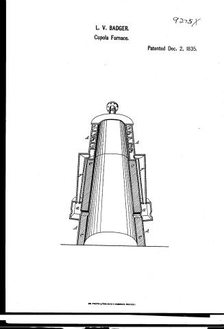
VO / 75. MB / Wins, hi, asts Q TWyores: / Windi-there x pregares / 9275-1 / DIVISIONL / 9275X / Its V. BAD GER / HIT aur I Cupola Furnace / Patented 2"Dec" 1135) / claim Is the double / cylaird ir at the tap of the / funance forming a eircust / chamber for the air / heating tha plact from the / flaws of the fund are / unevelop causing ou great / saving of fuel + time / 20 ) claim the / double cylinder to / body of furnaes / Dez / A. Cylinders / B.Hol (117 cylinder / privacion the escape / C. Bricklining / of the heat by the confined / D. Spirat-prate / air between the two cylinders / F. / I' Supplysings / palent fortic guly 711832 / G. air light chests / Made under the directions the comminine / of patents tim comformity with act 3"March 1837 / Minner zpatents
USPTO scan
The patent as scanned by the USPTO
-
 Page 1
-
 Page 2
-
 Page 3


U.S. Patent and Trademark Office · Google Patents
Show the transcription Hide (663 words)
Machine transcription (LightOnOCR) of the pages as scanned by the USPTO, most of them the handwritten copies made when the records were restored after the 1836 fire. Not checked; it can misread handwriting, so compare it with the scan.
Page 1.
L. V. BADGER.
Cupola Furnace.
Patented Dec. 2, 1835.
9275X

AM. PHOTO-LITHO. CO. N.Y. (OSBORNE'S PROCESS.)
Page 2.
9275X
Dec 2 1835 447
Leonidas W. Badger, of Portsmouth N.H.
Letters Patent
The Schedule referred to in these Letters Patent and making part of the same containing a description in the words of the said Leonidas Badger himself of his improvement in the Hot air and Conical Furnace.
To all to whom these presents shall come, We, the Governor that is Leonidas W. Badger of Portsmouth in the County of Rockingham and State of New Hampshire, has invented constructed and applied to use a new and useful improvement called the Hot air Conical Furnace, of which the following is a full and exact description.
The furnace consists of two conical cylinders about four feet inches in height, the bottom end of one three feet diameter, the top two feet, the other one inch in diameter less, having a space when placed on the bottom of about one inch. The bottom is arranged in the usual way of common conical furnaces, on the top of cylinders or body of furnace is a ring projecting with a moulding around each four inches, the thickness of the brick lining to receive the two cylinders, which I call the hot air cylinders, these are to be arranged that the outside shall be on a line with the furnace body and shall be half the height of the same, one other cylinder of the same length four inches less in diameter to be placed on a cone on the inside having a chamber for the air of four inches in the clear, which being the same as the thickness of the brick lining, will leave the regularity of the cone on the interior of the furnace equal and perfect. On the top of these air chamber cylinders, is to be a ring filled with the moulding, on the interior of this air chamber, is a special plate running entirely around several times, leaving the distance between of about four inches making more or less a circular pipe of four inches square, or it may be divided by partitions or any other mode that will give the continuous chamber for the air on the back side of the cylinders at the top and a hole is to be cast for the bottom pipe to be connected at the two opposite sides, on the bottom edge two holes are left for the supply pipes which end in air tight chests. These chests should be about eight inches square and four inches deep, secured at
Page 3.
143.
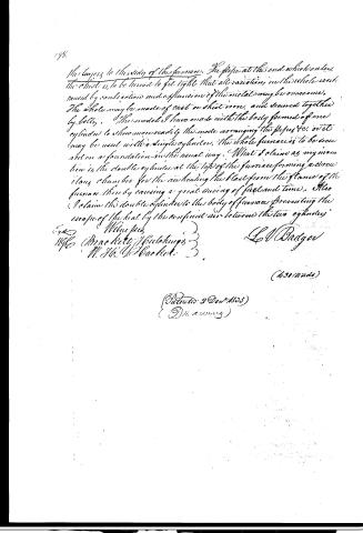
the layers to the sides of the furnace. The pipe at the end which enters the chest is to be turned to fit tight that all variations in the whole caused by contraction and expansion of the metal may be overcome. The whole may be made of cast or sheet iron, and secured together by bolts. The model I have made with the body formed of one cylinder to show more readily the mode arranging the pipes, &c. or it may be used with a single cylinder, the whole furnace is to be secured on a foundation in the usual way. What I claim as my invention is, the double cylinder at the top of the furnace forming a circular chamber for the air heating the blast from the flame of the furnace, thereby causing a great saving of fuel and time. Also I claim the double cylinder to the body of furnace preventing the escape of the heat by the confined air between the two cylinders.
Wm. J. Badger
1860 (Bracekett & Buldings)
W. H. & H. Bracekett
(680 words)
(Patented 2 Dec 1860)
(D. A. A. A. A.)
Published accounts: journal notice
Notice in the monthly list of patents
Journal of the Franklin Institute, new ser., vol. 17 (1836), p. 144 · View the page
735. Cupola Furnace.-L. V. Badger, Portsmouth, New Hampshire.
Published accounts: journal notice
Notice in the monthly list of patents, with remarks
Journal of the Franklin Institute, new ser., vol. 18 (1836), p. 35 · View the page
1. For a Hot Air and Cupola Furnace; Leonidas V. Badger, Portsmouth, Rockingham county, New Hampshire, December 2.
Remarks. This cupola furnace is to be in the usual form, and the upper part of it, above the brick lining, is to have concentric metallic cylinders, or rather truncated cones, standing four inches apart; the inner cone, at its lower end, being of the same diameter with the brick lining of the furnace body, so that the interior may be in a continuous line from top to bottom. A spiral partition is to run round within the space between the upper cones, leaving a distance of four inches between the coils, thus constituting a circuitous pipe of four inches square. Into the upper opening of this, the pipe from the bellows is to enter, and from the lower part pipes are to proceed down so as to conduct the heated air into chests, or boxes from which the tuyeres open into the furnace. The body of the furnace, surrounding the brick lining, is likewise to be a double case, with an inch space between them. The claim is to "the double cylinder at the top of the furnace, forming a circuitous chamber for the air, heating the blast from the flame of the furnace, thereby causing a great saving of fuel and time. Also, I claim the double cylinder to the body of the furnace, preventing the escape of heat by the confined air between the two cylinders." Various plans analogous to the foregoing, for heating air in cupola furnaces, have been carried into operation both here and in Europe. Of some of them we have particular accounts, of others nothing more than general descriptions; and how far the patentee has been anticipated in his particular mode of effecting his purpose we are not prepared to say. The second part of his claim we think ought to have been omitted, as a double case, with air confined between, to prevent the dissipation of heat, is an arrangement familiar to every man of practical science.
DATAMP: illustration
Illustrations from DATAMP


DATAMP (Directory of American Tool and Machinery Patents), via the Internet Archive · Archived DATAMP page
About this record
- Patentee
- Jim Shaw's X-patent list
- Date
- the Name and Date index of patents, DATAMP, USPTO records
- Invention
- DATAMP
- Listed in
- the Name and Date index of patents, DATAMP, USPTO records, Jim Shaw's X-patent list, the Journal of the Franklin Institute, Burke's List of Patents (1847)
- The residence comes from the Franklin Institute's journal.
- Burke's 1847 Patent Office list gives the same patent.