

Drawings and documents
National Archives restored drawings: drawing
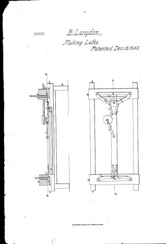
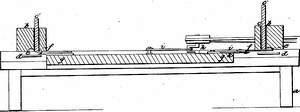
B. Langdon's Patent Drawing for a Machine for Cutting and Splitting Laths

National Archives, Restored Patent Drawings (Record Group 241) · Full-size scan at the National Archives · Catalog record
Show the text on the drawing Hide (106 words)
Words on the drawing as machine-read by the National Archives; not checked. Useful mainly for searching.
144. WOOD WORKING MACHINES. / Securet Sath / Slicers, Reciprocating. / B. O LANGDO DAY / 2ol 21. hage 97- / #1- / Laths / eacented) 15 Dect 1535 / classifica TION / 92891 / DIVISION / 9289 / c' / sections throng. .C.D. / a. Frame 7, orthandblock. c sloten d:c' Biardinslot / d. Georges. e Stechplate allachento under side of headblock / f. Knives. I sliding bar orbeam. h Crank. z stracticeline / K Metaphlate having adjusting sciens- / Section through A.B. of sectional elevation / Patent office Sune28th 18112 / Strickland Del / Mach under the direction of the commonen of / Patents in conformity with act g's' March 1837 / Communicate of Paters
USPTO scan
The patent as scanned by the USPTO
-
 Page 1
-
 Page 2
-
 Page 3
-
 Page 4
-
 Page 5


U.S. Patent and Trademark Office · Google Patents
Show the transcription Hide (1,453 words)
Machine transcription (LightOnOCR) of the pages as scanned by the USPTO, most of them the handwritten copies made when the records were restored after the 1836 fire. Not checked; it can misread handwriting, so compare it with the scan.
Page 1.
9289X
B. Langdon,
Making Laths.
Patented Dec. 15, 1835.
AM. PHOTO-LITHO. CO. N.Y. (OSBORNE'S PROCESS)
Page 2.
Barnabas Langdon
The schedule referred to in these Letters Patent, any making part of the same, containing a description in the words of the said Barnabas Langdon himself of his improvement in the Machine for cutting or splitting Laths.
To all to whom these presents shall come,
Be it known that I, Barnabas Langdon of the City of Troy in the County of Rensselaer and State of New York, have invented a new and useful improvement in Machinery for Cutting or Splitting Laths, and that the following is a full and exact description thereof.
A rectangular frame is to be provided, about eighteen feet long and seven feet wide, more or less. The height of the frame is to be such as the several parts of it with its fixtures and appendages, of such dimensions and materials, and so disposed, as in judgment shall be adapted to the operating part of the Machinery, to the process as well as to the convenience of attending to and conducting the same. The Laths, upon the principle of the improvement, are to be cut or separated from the under edge of a board or plank to be prepared and placed in the machine for the purpose, by means of knives or cutting tools, hereafter to be described. In order to effect this, there should be a cross beam or head block upon the upper part of each end of the frame, with a slot or opening through it from the upper to the lower surface vertically, and in length to an extent a little more than equal to the length of the lath which is to be cut by the machine. This slot, being for the purpose of having the lath placed within it, should be near the inside of the cross beam, and of such width as to allow the board to drop by its own weight or be easily
Page 3.
precise down upon guages provided underneath for the lower edge of the board to rest upon, as the laths are successively cut or separated from it. Two knives or cutting tools are to be employed in separating each lath from the board. One end of each knife is to be secured to the plate (hereafter to be described) attached to the under side of the head block near the side of the frame, by a screw or pin, or other flexible joint, so as to allow the other or inner end to move horizontally one way or the other upon this joint as the centre of its sweep. The edges of the knives are to be placed outward, and their action in separating the lath from the board, is, by drawing back their inner end from the head block far enough to allow the board to drop down in the slot before the edge of the knives upon the guages or rests provided for it, and then having their inner ends forced back till the entire length of edge of each knife passes under or a little beyond the slot. By this way the lath is separated from the board, and when the knives are again drawn back the board will also again drop to its guage ready for the production of another lath. A steel plate is to be attached to the under side of the head block out side of the slot—the inner edge of which, or the lower angle of it being made smooth, is to constitute the lower edge of the slot, on that side against which the knives are to act, they being made to pass under and in contact with it thereby causing the plate to perform in effect the counter part of the cutting process which separates the laths from the board. In order to give the edge of each knife a sawing motion as it cuts off the lath, the blade should be formed by inclining or curving its outer end forward of the line of its edge so to have the screw or pin which secures that end to the steel plate under the head block.
Page 4.
pass through it for that purpose, and thus fix the flexible joint at a discretionary distance, for some of such line crossing—by. The length of the knives is to be such as to bring the knife ends nearly in contact with each other, as they pass in together under the head block. In order to give them the motion required for cutting or separating, a sliding bar or beam is to be provided and placed horizontally in the centre of the frame, upon fixed lines provided for it, as there may be according to the foregoing description, at each end of the frame, it being the object of the present improvement to have it so, this slide should extend in length nearly to each pair of knives, so as to give effect to both. This is to be done by giving a reciprocating movement to the slide on the direction of its length by means of cranks which shall be made to revolve near it for that purpose, and connecting them together by a shackle bar or sweep, the same being attached to the slide by a joint or other flexible joint, adapted to such operation, and the same motion is to be communicated to the inner ends of the knives by connecting each to one of a shackle bar, while the other end of the same bar is to be attached to the upper surface of the slide, both by pin or other flexible joint. The sweep to be given to the cranks and the length of the shackle bar, and also of those connecting the slide with the knives being sufficiently indicated by the purposes to be answered by each, they are here left without further description as matters of judgment to be exercised in their construction. So also of the moving power of the machinery and of its application thereto. It may be by gears, bands, or otherwise at discretion. In order to adjust the edges of the knives to the plate under the head block, a plate of metal may be attached to the upper surface of each end of the slide through which an adjusting screw may be extended, so as to bear against the under side of the blade or plate.
Page 5.
100.
of each knife, the inner ends of which in its connection with the shackle bar being brought on to the end of the slide sufficient for that purpose. In this way the knife may be raised or depressed, as occasion shall require. So also the grooves on which the board rests, as it drops down in the slot before the knives, being made elastic, may in like manner be illustrated or depressed by means of a screw passing through a fixture of the frame against the under side of each groove, and the thickness of the lath thereby regulated. As an alternative improvement, instead of two knives at each end of the frame, as above described, for cutting or separating each lath, one knife or cutting tool only may be used. In which case, its inner end being like the other attached to the plate of the head block near the side of the frame, the length of the knife being equal to the length of the lath to be cut by it, the other end is to be operated in the same manner, or upon the same principles. One of such single knives being fixed at each end of the frame, & like the double knives connected with the slide, it is obvious that in either case a lath will be produced at each reciprocating movement thereof, one at each end alternately. The knives or cutting tools, except about four inches wide of the blade or edges, may be of cast iron, suitably prepared, and the blade attached thereto by screws or otherwise.
For a further illustration of my invention, I refer to the model & drawing of the same deposited in the patent office.
What I claim as my own invention, and not previously known in the above described machine, is the machine itself, and the manner of cutting lath as above specified and described.
Witnesses
Daniel Whiting
Allen Wright
B. Langdon
(1524 words)
Not subject to any alteration to be drawn
Published accounts: journal notice
Notice in the monthly list of patents
Journal of the Franklin Institute, new ser., vol. 17 (1836), p. 144 · View the page
754. Laths, cutting.-Barnabas Langdon, Troy, N. Y.
Published accounts: journal notice
Notice in the monthly list of patents, with remarks
Journal of the Franklin Institute, new ser., vol. 18 (1836), p. 40 · View the page
20. For a Machine for cutting or splitting Laths; Barnabus Langton, Troy, New York, December 15.
Remarks. A horizontal bench, or frame, is to be made, which may be sixteen feet long and seven wide; and at each end of this there is to be a head-block, against which the laths are to be cut. The cutting is to be made from the edges of boards, sawed of a proper length, there being two cutting knives at each end of the frame. These cutting knives meet in the middle of the board, as the lath is cut, their outer ends working on pins attached to the head-block or frame, and their inner ends on similar pins connected with a sliding bar extending along the middle, and from one end of the frame to the other. The sliding bar is worked backward and forward, horizontally, by a crank motion, so that when the knives at one end are cutting a lath, those at the other are being withdrawn to allow the board to descend American Patents for December, with Remarks. for a new cut. The pieces of board are passed into a slot edgewise, at either end of the frame, and descend by their own gravity, or to a gauge which determines the thickness of the lath. It is proposed sometimes to use a single knife at each end, which knife must in that case, be the whole length of the lath. The claim made "in the above described machine, is the machine itself, and the manner of cutting lath above specified and described." Such a claim, we apprehend, must be understood to include not only the combination, but also the several parts as described; in which case it is much too broad, as the cutting of laths from the edges of boards, fed to the knife in a similar way, is not new. In some instances the knives used have formed a very obtuse angle in the middle, so as to cut first at the two ends, and this plan we think much preferable to the jointed knife which is at every instant altering its cutting angle. Still, should the machine before us be preferred, we think that enough of novelty might be pointed out upon which to found a valid claim.
DATAMP: illustration
Illustrations from DATAMP

DATAMP (Directory of American Tool and Machinery Patents), via the Internet Archive · Archived DATAMP page
About this record
- Patentee
- DATAMP
- Date
- the Name and Date index of patents, DATAMP, USPTO records
- Invention
- DATAMP
- Listed in
- the Name and Date index of patents, DATAMP, USPTO records, Jim Shaw's X-patent list, the Journal of the Franklin Institute, Burke's List of Patents (1847)
- The Franklin Institute's journal spells the name differently.
- Burke's 1847 Patent Office list gives the same patent.