

Drawings and documents
National Archives restored drawings: drawing
Solomon Andrews' Patent Drawing for a Lock

National Archives, Restored Patent Drawings (Record Group 241) · Full-size scan at the National Archives · Catalog record
Show the text on the drawing Hide (68 words)
Words on the drawing as machine-read by the National Archives; not checked. Useful mainly for searching.
a o M A N ID R W S, / 11 0 0 / 9310 / DIV ISION. / 9310 / Patênted 11. th Jan's 1836. / FIG.1. / S. / U. / B. / FIG - 2. . / FIG.3. / I. / Gt. / J. / FIG.14 / FIG. 4. FIG.S. FIG.6 FIG.7. FIG.8. FIG.9. / 1. / 2. / 3. / 4. / 5. / G. / 1. / 3. / 7. / 8. / 2. / 3. / 9. / 10. / 11 / 1. / 12. / 1. / FIG.10. FIG.11. FIG.12. FIG.13. / 13 / 14 / 3. / 15. 1 2 3. 4. / claim - The delech / constructed / will / if too piece to however is applied.
USPTO scan
The patent as scanned by the USPTO
-
 Page 1
-
 Page 2
-
 Page 3
-
 Page 4
-
 Page 5
-
 Page 6
-
 Page 7


U.S. Patent and Trademark Office · Google Patents
Show the transcription Hide (2,706 words)
Machine transcription (LightOnOCR) of the pages as scanned by the USPTO, most of them the handwritten copies made when the records were restored after the 1836 fire. Not checked; it can misread handwriting, so compare it with the scan.
Page 1.
No Printed Specification Available
S. Andrews,
Lock.
Patented Jan. 11, 1836.
9310X
Fig: 1.
<!-- Image: Fig: 1. -->
Fig: 2.
<!-- Image: Fig: 2. -->
Fig: 3.
<!-- Image: Fig: 3. -->
Fig: 14.
<table>
<tr><td>1</td><td>1</td><td></td><td></td></tr>
<tr><td>2</td><td>2</td><td>3</td><td></td></tr>
<tr><td>3</td><td></td><td></td><td></td></tr>
<tr><td>4</td><td></td><td></td><td>4</td></tr>
<tr><td>5</td><td>1</td><td>2</td><td></td></tr>
<tr><td>6</td><td>1</td><td>2</td><td>4</td></tr>
<tr><td>7</td><td>1</td><td></td><td></td></tr>
<tr><td>8</td><td>2</td><td>3</td><td>4</td></tr>
<tr><td>9</td><td>2</td><td></td><td></td></tr>
<tr><td>10</td><td></td><td>3</td><td>4</td></tr>
<tr><td>11</td><td>1</td><td>2</td><td>3</td></tr>
<tr><td>12</td><td>1</td><td>2</td><td>4</td></tr>
<tr><td>13</td><td>1</td><td></td><td></td></tr>
<tr><td>14</td><td>2</td><td>3</td><td>4</td></tr>
<tr><td>15</td><td>1</td><td>2</td><td>3</td></tr>
</table>
Fig: 4. Fig: 5 Fig: 6. Fig: 7. Fig: 8. Fig: 9.
<!-- Image: Fig: 4. Fig: 5 Fig: 6. Fig: 7. Fig: 8. Fig: 9. -->
Fig: 10. Fig: 11. Fig: 12. Fig: 13.
<!-- Image: Fig: 10. Fig: 11. Fig: 12. Fig: 13. -->
A.M. PHOTO-LITHO. CO. N.Y. (OSBORNE'S PROCESS.)
Page 2.
9310 X
Jan. 11. 1836
Solomon Andreas of Little Amboy New Jersey
Letters Patent
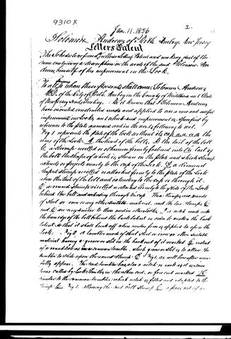
The Schedules referred to in these Letters Patent and making part of the same containing a description in the words of the said Solomon Andreas himself of his improvement on the Lock.
To all to whom these presents shall come, Solomon Andreas M.D. of the City of Little Amboy in the County of Middlesex and State of New Jersey sends Greeting. Be it known that Solomon Andreas have invented constructed made and applied to use a new and useful improvement in Locks and which said improvement is specified by reference to the plate annexed and in the words following to wit.
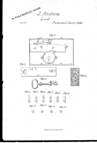
Fig 1 represents the plate of the lock without its cap a a. a a the rims of the lock. A the head of the bolt. B the tail of the bolt C a stamp rivetted or otherwise firmly fastened into the tail of the bolt the shape of which is shown in the plate and which stamp extends or projects nearly to the cap of the lock. D a diamond shaped stamp rivetted or attached firmly to the plate of the lock above the tail of the bolt and extending to the cap or through it. E a round stamp rivetted or attached firmly to the plate of the lock behind the bolt and extending through the cap. These stamps are made of steel or iron or any other suitable material, and the two stamps C and E are very similar to those used in other locks. F a notch made into the lower edge of the bolt behind the back tangent in order to weaken the back tangent so that it shall break off when undue force is applied to open the lock. Fig 2 a lamble made of steel steel or iron or other suitable material having a groove or slot in the back end of it marked G instead of a round hole as in a common lamble, which groove or slot is to allow the lamble to slide upon the round stamp C. Fig 3 as well hereafter more fully appears. The said lamble has also a notch or rack as it is sometimes called by Locksmiths in the other end, or fore end marked H similar to the common lamble which notch is fitted and adapted to the stamp C. Fig 1. allowing the said bolt stamp C to press out of or
Page 3.
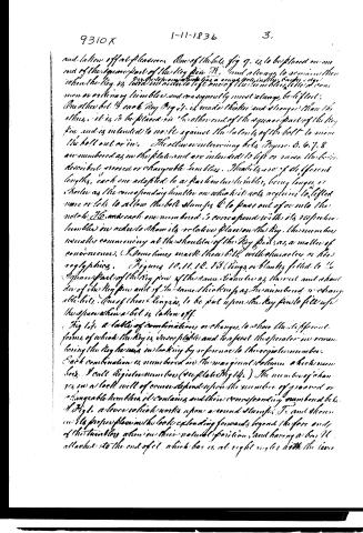
into the said notch or rack as the ball is thrown out or thrown back by the key when the tumbler is properly lifted and which notch is so constructed as to hold fast the said stump C by the weight of one end of the tumbler resting on the stump so as to be drawn out by the said stump with the ball when not lifted by the key through said groove or slot G, allowing of such sliding motion to the tumbler on the stump C. Fig 1. The said tumbler has also a fin or projection on its upper edge marked H which fin or projection is formed between two notches in the said upper edge of the tumbler the intervening portion or projection constituting the said fin. This fin or projection is so situated or placed on the upper edge of the tumbler as to be immediately behind the stump D. Fig 1. When the tumbler is placed in the lock with the ball thrown back and immediately before the said stump D, when the ball is thrown out and the tumbler drawn out with it as herein before described. The use of the said fin is to prevent the ball being thrown back by the said fin striking against the stump D. Fig 1. When the tumbler is lifted after being drawn out with the ball, the lower edge of the tumbler marked J is straight not concave nor convex as is the case in the usual or common tumbler where the key acts upon it. In the tumbler of one lock all the lower edges of them correspond and are similar so as to form a smooth and regular or even surface particularly in that part or portion of them opposed to the key hole or where the key acts upon them and in the several tumblers of one lock all the mouths of the notches marked I K. Fig 2. are placed at different heights in their several forcements so that the said tumblers shall require to be lifted to different heights or distances to allow the ball stumps to pass into or out of the several notches. Fig 3. The key without any bits on it the end or key pin being square and marked R. and having a nut L screwed on the opposite end of it, which nut is round and forms a part of the key pin and corresponds in diameter with the round shoulder R of the said key pin from whence the key pin originates. Figures 4, 5, 6, 7, 8, 9. The bits with a square hole in each fitted to the square part of the key pin so as to be put on.
Page 4.
and taken off at pleasure. One of the bolts, fig 9, is to be placed on one end of the square part of the key pin H, and always to remain there when the key is turned in order to keep one of the tumblers (the common or ordinary tumbler) and consequently must always be lifted. Another bolt, B each key Fig 1, is made thicker and stronger than the others, it is to be placed on the other end of the square part of the key pin and is intended to work against the sides of the bolt to move the bolt out or in. The other intervening bolts, Figures 5, 6, 7, 8 are numbered as in the plate and are intended to lift or raise the bolts described, movable or changeable tumblers. These bolts are of different lengths, each one adapted to a particular tumbler, being longer or shorter as the corresponding tumbler on which it acts requires to be lifted more or less to allow the bolt stamps C to pass out of or into the notch JQ, and each one numbered to correspond with its respective tumbler in order to show its relative place on the key, the numbers usually commencing at the shoulder of the key pin, as a matter of convenience. I sometimes mark these bolts with characters or hieroglyphics. Figures 10, 11, 12, 13 (rings) are blankly filled to the square part of the key pin of the same thickness as the bolt and shoulder of the key pin and of the same thickness as the numbered or changeable bolts. One of these rings is to be put upon the key pin to fill up the space when a bolt is taken off.
Fig 14, a table of combinations or changes, to show the different forms of which the key is susceptible and to assist the operator in remembering the key he uses in locking by reference to the register numbers. Each combination is numbered in the marginal column which numbers I call Register numbers (see plate Fig 14). The number of changes in a lock will of course depend upon the number of grooved or changeable tumblers it contains and their corresponding numbered bolts.
Fig 1, a lever which works upon a round stamp F, and shown in its proper place in the lock extending forwards beyond the fore end of the tumblers when in their natural position, and having a bar H attached to the end of it which bar is at right angles with the lever
Page 5.
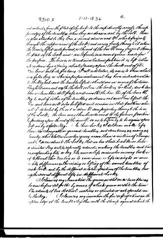
and extends from the plate of the lock to the cap directly across the upper edges of the tumblers when they are drawn out by the bolt. There is also attached to this lever a second wire or rod W, which projects through the upper arm of the lock, and moves freely through it when the lever is lifted or depressed, or the end of the bar W may project through the plate of the lock and work freely in a groove or groove made for the purpose. The lever is retained in a neutral position it is left either up or down by a spring which bears upon the back end of it.
This lever with its fixtures I call a detector, its use is to show whether a false key or some improper instrument has been introduced into the key hole and the tumblers lifted. Should one or more of the tumblers be drawn out with the bolt when the lock is locked, each tumbler or tumbler will pass underneath the bar W, of the lever S, Fig 1, and if either of the tumblers so drawn out are then lifted the bar and lever will also be lifted and remain in that position unless to be detected by the second wire V, same projecting through the arm of the lock. The lever may then be returned to its former position by pressing upon the end of the wire V, so as to be ready to be again operated on by a false key. In these locks I seldom make keys than are changeable or grooved tumblers, and sometimes as many as twenty, which latter number gives more than a million of changes and I so construct the locks that no two shall be alike or have a similar key unless especially ordered, making the tumblers and their corresponding bits or key bits more or less in number in every lock or of different thicknesses or to have more or less in weight or more or less difference in the raising or lifting of the several tumblers of each lock, and by the different relative positions of the tumblers having the several different lifts in different locks.
I claim as my invention the groove or slot in a tumbler as herein before set forth by means of which groove or slot the tumbler admits of two distinct motions or operates or not operates on by the key. I claim as my invention the pin or projection on the upper edge of the tumbler together with the stump against which the
Page 6.
said false projection strikes and meets resistance when the tumbler is improperly operated upon by the key or other instrument.
I claim as my invention the similarity of straight and even and regular edges of the several tumblers in one lock forming a regular surface in that part or portion of them exposed to the key hole where the key operates upon them which is the notch or notching on the fore ends of the tumblers so constructed in relation to the bolt stump as to require the said tumblers to be lifted different heights or distances in order to allow the bolt stump to pass into the said notches when the bolt is thrown back by which regular and even surface of the lower edge of the tumblers a false impression is given as to the formation of the key.
I claim as my invention the dissimilarity in the length of the bits of a key which operate upon the similar even and regular surface edges of the tumblers, but not so as to correspond with the irregular mouths of the notches on the tumblers at the bolt stump where no impression of them can be taken through the key hole.
I claim as my invention the manner of changing the key by taking off the bits and substituting things instead thereof by which blank spaces left in the key the tumblers corresponding to those absent bits are not lifted when the key is turned, and by which changes in the key the lock is locked differently, and so that no other formation of the same key will unlock the lock.
I claim as my invention the latter so many or combinations as hereinbefore set forth as applied to the purpose of changing the key to a lock.
I claim as my invention the herein before described device for ascertaining whether a false key or other improper instrument has been applied to the lock to lift the tumblers.
And I further claim as my invention the aforesaid application of the several parts of the herein before described lock, and I also claim as my invention the weakening the back talent of the bolt so that it shall break off when too much force is applied to force open the lock.
In testimony that the above is a true specification of my said
Page 7.
improvement as above described. I have hereunto set my hand this thirtieth day of November in the Year of our Lord one thousand eight hundred and thirty six.
Witnesses:
Thomas
Nicholas Lafarge
Henry D. Beddie
Solomon Andrews
(2324 Words)
(Granted January 11, 1836)
Drawing
About this record
- Patentee
- DATAMP
- Date
- the Name and Date index of patents, DATAMP, USPTO records
- Invention
- DATAMP
- Listed in
- the Name and Date index of patents, DATAMP, USPTO records, Jim Shaw's X-patent list, Burke's List of Patents (1847)
- Burke's 1847 Patent Office list gives the same patent.