

Drawings and documents
National Archives restored drawings: drawing
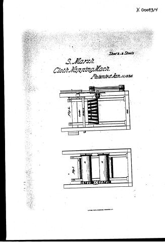
Stephen Marsh's Patent Drawing for a Machine for Napping Cloth


National Archives, Restored Patent Drawings (Record Group 241) · Full-size scan at the National Archives · Catalog record
Show the text on the drawing Hide (64 words)
Words on the drawing as machine-read by the National Archives; not checked. Useful mainly for searching.
Sheet 1. $4- Tex / 9314.4 / Chiphen Mursh / DIVISION. / Napping Cloth. / Patented 11th January 1836 / 9314 X / Eig 1. / Fig 2 / 19 / 18, / 0.7 / 17 Lever / the / 13 / 13. / Girder / Girder / 15 / 12 / HAY / 75 / 03 / 13 / Sill / Sill / OIR
Sheet 2. close Functive / napping / 9314 X / march you 11,1836 / CLASSIFICATION / June / 9314x / DIVISION. / Fig. 3. / Fis 4. / Sirder / (Loth / Cylinder / 13 / to / Roller 16 / 72 / C'loth / Cylinder 13 / lo / adjusting / Sill / Sill / DIR
USPTO scan
The patent as scanned by the USPTO
-
 Page 1
-
 Page 2
-
 Page 3
-
 Page 4
-
 Page 5
-
 Page 6


U.S. Patent and Trademark Office · Google Patents
Show the transcription Hide (1,308 words)
Machine transcription (LightOnOCR) of the pages as scanned by the USPTO, most of them the handwritten copies made when the records were restored after the 1836 fire. Not checked; it can misread handwriting, so compare it with the scan.
Page 1.
X6009314
S. Marsh.
Cloth Napping Mach.
Patented Jan. 11, 1836.
Sheet 1 & 2 Sheets.
Fig. 2
Fig. 1
A. PETER, PRINTED AT WASHINGTON, D.C.
Page 2.
X 00093/4
S. Marsh.
Cloth Napping Mach.
Patented Jan. 11, 1836.
Sheet 2. & Sheet 3.
Fig. 1
Fig. 2
A. PETER, PHOTO-LITHOGRAPHER, WASHINGTON, D. C.
Page 3.
9314X
Jan 11, 1836
Stephen Marsh of Jerico Vermont
Letters Patent (Patented January 11, 1836)
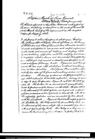
The Schedule referred to in these Letters Patent and making part of the same, containing a description in the words of the said Stephen Marsh himself of his improvement in the complete Nappe for Napping cloth.
To all persons to whom these presents shall come, Greeting.
Be it known that I Stephen Marsh of Jerico in the County of Chittenden and State of Vermont have Invented, constructed, made and applied to use a new and useful improvement in the mode and manner of Napping and dressing cloth by one continued operation with the napping and dressing in completed, which is known and denominated the complete Nappe: Which said improvement is described and specified in the words and figures following, to wit: Figures one and two represent the two ends with all the frame work and machinery seen in those directions. And figures three and four represent the two sides of the frame and machinery as seen in those directions. The drawing is about one half the size of the actual size which is found to be suitable in practice, but may be varied in size to suit the operator. Figure 3. exhibits the stollery index 13. The pulleys 10, on one end are to secure friction bands to produce suitable tension on the cloth. The other wheels at the other end of the cloth cylinders are to gear into a special cylinder or screw, a section of which is seen at 12, & to 14 are the adjusting cylinders and are connected by their pivots with the inner posts — Figure 4. Exhibits the napping cylinder 15, the Roller 16, the Pulley called the driven Pulley 201, on the other end of the same shaft this is connected by a band with and carries pulley 202. This Pulley is a long one and carries the bands running from the same to pulleys 30, 40 & 5.
Page 4.
The pulley 3 is fast on the shaft of the nappling cylinder 15, and the pulleys 4 & 5 are loose. When the nappling cylinder is required to go one way the open band is placed on pulley 3, and when it is required to go the other way the open band is slipped on to a loose pulley, and the cross band slipped on to pulley 3. On the same shaft of pulley 6, is a small pulley 6, freely steered above pulley 7, to which it is connected by a band and on the same shaft, with pulley 7, is a small pulley 8, which is connected by a band with pulley 9, and on the inside of pulley 9 and concentric therewith is a bevel wheel attached to the said pulley, and turning therewith on an axis of rotation. The other bevel wheel connected with the above is on the shaft of the screw or spiral cylinder 12 in the end of which is a small quidgen or pivot which passes through the said axis of rotation and thereby keeps both wheels in due proximity.
Figure 1 exhibits an end view of the frame to which the machinery is attached and a side view of pulleys No 1, 7, 9 & 20, and an end view of the two cloth cylinders No 13. Also the adjusting cylinders 14, attached by their pivots to the inner posts, and the nappling cylinder 15, also the lever 17 which is attached to the end of the Roller 16. There is turned into the roller 2 uprights No 18 connected by scissor joints with the inner posts by long levers or scissor pieces. The cloth being stretched over the adjusting cylinders into those the cloth line, as marked from 14 to 14. Then by raising the lever 17 will bring the cloth in contact with the nappling cylinder 15, and by lowering the said lever will make the cloth recede from the said cylinder. For the purpose of holding the lever in its proper place a number of holes are bored in the post, into which an adjusting pin may be put and moved as occasion may require. On an adjusting cord or strap answers the same purpose. On pulley 9 is seen the bevel gear above described attached to the screw or spiral cylinder as aforesaid. Figure 2 exhibits the opposite end of the frame from figure 1, and also a side view of pulleys No 1, 2, 3, 7, 8, and 9, and also a view of the spur wheels 19, at the ends of the cloth cylinders, and the screw or spiral cylinder, passing between them and to be geared into either as occasion may require. Also an
Page 5.
9314 X 1-11-1836 3. 23.
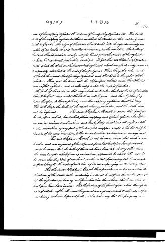
rear of the napping cylinder 16, and one of the adjusting cylinders 14; The dark side of the napping cylinder is the side on which the cards, another napping material is fixed. The edges of the cards should be let into the cylinder nearly one eighth of an inch, so as to leave the card convex in the middle. The teeth of the card should radiate nearly in right lines from the center of the cylinder or have but a small inclination or slope. To put this machine in operation, first wind the cloth on the lower cloth cylinder, which may be done by a crank temporarily attached to the end of the gear box. Then bring the other end of the cloth around the adjusting cylinders and attach it to the upper cloth cylinder. Then gear the screw into the upper gear wheel, until the cloth has run on that cylinder, and so alternately until the nap is finished.
The back of the cards, or that way which will take the least hold of the cloth should be first used until the cloth is well begun, and then by changing from the open to the crooked band, run the napping cylinder the other way. This will keep the teeth of the cards always in order, and the cloth will not be injured.
The said Stephen Marsh is aware that pulley bands, spur wheels, bevel wheels, plain napping, and spiral cylinders have been in use in various combinations, and hereby fully disclaims all right or title to the invention of any part of the complete napier except what he truly believes is of his own invention, either in combination, combination or arrangement.
The said Stephen Marsh is not however aware that such a combination and arrangement of the different parts has heretofore been proposed, nor is he aware that the teeth of the cards have been set at any other than the usual angle which from examinations appears to be about 48°, nor is he aware that the pivot of one bevel or other wheel has in any case been made to pass through the axis of rotation of its accompanying or accompanying wheel.
He the said Stephen Marsh therefore claims as his invention the direction of the card teeth, radiating in direct lines from the center or axis of the cylinder or having a left inclination than those which are now or heretofore have been in use, also the passing of the pivot of one wheel through the axis of rotation of the other and the general arrangement and combination of the machinery as herein before set forth. In testimony that the foregoing is a
Page 6.
9314 X 1-11-1836 4.
24.
Specification of my said improvement and invention as herein before described. In witness whereof I have set my hand this 12th day of November 1835.
Witnesses:
E. R. Johnson
John Johnson
Stephen Marsh
(1038 words) (Patented January 11, 1836.)
(Rec’d & Recorded as above September 12, 1835)
(Drawing)
Published accounts: journal notice
Notice in the monthly list of patents, with remarks
Journal of the Franklin Institute, new ser., vol. 18 (1836), p. 39 · View the page
14. For a Machine for Cutting Straw, and Thrashing and Win nowing Grain; Leonard Marsh, Hartford, Windsor county, Vermont, December 9.
Remarks. This is a combined machine intended, in general, to cut the straw into lengths, like an ordinary straw cutter, and to thrash the grain from it, after which the grain and straw are to be separated by winnowing, in the usual way. When the grain is to be thrashed only, the cutting knives are to be removed, the thrashing part remaining, to effect that object.
Published accounts: journal notice
Notice in the monthly list of patents, with remarks
Journal of the Franklin Institute, new ser., vol. 18 (1836), p. 114 · View the page
11. For Dressing and Napping Cloth; Stephen Marsh, Jerico, Chittenden county, Vermont January 11.
Remarks. This machine in its general construction, resembles those now in common use for the napping of cloth, but the patentee thinks that considerable advantage is derived from causing the card teeth on the napping cylinder to American Patents for January, with Remarks. stand in the direction of radii, or nearly so, from its centre. "Said Stephen Marsh, claims as his invention, the direction of the card teeth, radiating in direct lines from the centre, or axis of the cylinder, or having a less inclination than those which are now, or heretofore have been, in use. Also the passing the pivot of one wheel through the axis of rotation of the other, and the general arrangement and combination of the machinery as set forth." We doubt the validity of the claim to the radiating, or nearly radiating, teeth, as we believe that they have been frequently so employed. The other point claimed is a mere matter of arrangement, not at all necessary to the action of the machine.
About this record
- Patentee
- DATAMP
- Date
- the Name and Date index of patents, DATAMP, USPTO records
- Invention
- DATAMP
- Listed in
- the Name and Date index of patents, DATAMP, USPTO records, Jim Shaw's X-patent list, the Journal of the Franklin Institute, Burke's List of Patents (1847)
- The Franklin Institute's journal gives a different date.
- Burke's 1847 Patent Office list gives the same patent.