

Drawings and documents
National Archives restored drawings: drawing
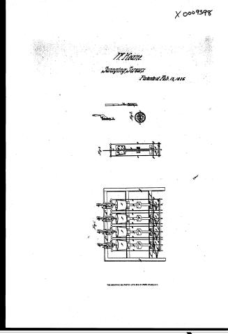
W. Keane's Patent Drawing for a Machine for Making Screws

National Archives, Restored Patent Drawings (Record Group 241) · Full-size scan at the National Archives · Catalog record
Show the text on the drawing Hide (46 words)
Words on the drawing as machine-read by the National Archives; not checked. Useful mainly for searching.
80. METAL-ROLLING, / krevies / Rotting screw threads. / W KEANE'S / CLASSIFICATION / 250 / Reisure sta.2. / 9398 X / Wachine for making forcus / DIV ISION. / Patentel F'ebs. 13th 1836 / Reieved / of / of / As / chamber for / .A / In
USPTO scan
The patent as scanned by the USPTO
-
 Page 1
-
 Page 2
-
 Page 3
-
 Page 4


U.S. Patent and Trademark Office · Google Patents
Show the transcription Hide (1,202 words)
Machine transcription (LightOnOCR) of the pages as scanned by the USPTO, most of them the handwritten copies made when the records were restored after the 1836 fire. Not checked; it can misread handwriting, so compare it with the scan.
Page 1.
X 0009398
M. Heane.
Swaging Screws
Patented Feb. 13, 1856
THE GRAPHIC CO. PHOTO-LITH. 30 & 41 PARK PLACE, N.Y.
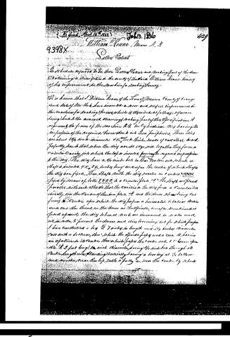
Page 2.
Filed April 16th 1835
William Keane, Muncie, N.Y.
9398X
Sellers Patent
In Schedule referred to in these Letters Patent, and making part of the same, Containing a description in the words of the said William Keane, having of his improvement in the machine for making Pencils.
It is known that I, William Keane, of the Town of Muncie, County of Orange, and State of New York, have invented a new and useful improvement in the machine for making Pencils, which is described as follows: Reference being had to the annexed drawings, making part of this Specification, A represents the frame of the machine B.B. the Cylindrical Dies having the impression of the respective Pencils, with their peripheries. These dies are about 1 3/4 inches diameter, 4 1/2 inches thick, made of cast steel, hard, perfectly smooth, so that when the dies are set edge wise together they form a circular Cavity into which the top is inserted, forming the required impression to the dies. The dies have a 1/4 inch hole in their centers, into which is shaped a shaft C.C., 2 1/2 inches long, and upon the center of which all the dies are fixed. Three Shafts with the dies revolve on centers D.D.D.D. fixed by means of bolts E.E.E.E. to a circular plate F.F. The Shafts are placed parallel with each other so that the circles in the dies form a concentric circle, so the centers of the iron plate F.F. and the iron shafts being cut forming the Center upon which the dies perform a horizontal & vertical motion, and one the thread on the iron as the spindle, so as to be driven in forward upwards, the dies when at work are immersed in a molten wax, in order to prevent the wax and dies becoming hot for which purpose I have constructed a box G, 7 inches in length and 5 1/2 inches diameter, cast with a bottom, H, which the Spindle passes under a cover, I, having an aperture in its center through which passes the center rod, J, 1 1/2 inches long, 1/2 inch diameter, having 1/2 inch hole through its center, lengthwise, standing vertically, having a bearing at the bottom and another near the top, with a pulley S, near the center, by which
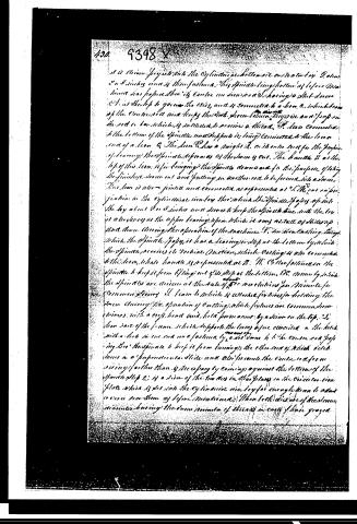
Page 3.
It is driven by projection into the cylindrical hollow or box D about 2 or 3 inches and is then fastened. This spindle being hollow as before mentioned has before shown its centre on a screw A having a slot across C1 at the top to go over the axis, and is connected to a beam B, which beam of the centre rod and keeps the work shown thereon in its place and prop on the rod or bar which is intended to receive a thread. D. Also connected to the bottom of the spindle and supports it, being connected to the lower end of a lever C. The lever C has a straight A in its outer end for the purpose of leaning; the spindle appears as if the lever is out. The handle B at the top of the lever is for bringing the spindle down and for the purpose of taking the finished thread out and putting in another one to be formed into a thread. This lever is also jointed and connected as represented at 2. The cut on page 10 in the cylindrical box by the wheel the spindle passes up into the box about 2 or 3 inches and serves to keep the spindle true with the box as a bearing at the upper bearing upon which it moves as well as turns up and down during the operation of the machine. V. is a wire casting through which the spindle passes, it has a bearing or stop at the bottom by which the spindle receives its vertical motion, which casting is also connected to the lever, whose handle is represented at B. W. is the fastener on the spindle to keep it from lifting out of its stop at the bottom. DC. is a wire by which the spindle is driven at the rate of about 5 revolutions per minute for common sewing. A beam or wheel is attached for time for holding the lever during the operation of cutting, while fixtures are common screw driven, with a cross head and bolt permanently by a screw on the top. 2. The rear part of the frame which supports the lever before described is the block with a hole in one end and a fastening by a set screw to the centre rod passing through the spindle to keep it from turning; the other end of which is attached in a perpendicular slide and also prevents the centre rod from rising farther than is necessary by coming against the bottom of the spindle stop C. is a piece of the two bars in their places on the circular iron plate which is set into the cylindrical box for enough room to admit a cross bar there as before mentioned. These both are made of steel, the diameter having the same number of threads on each of their grooves.
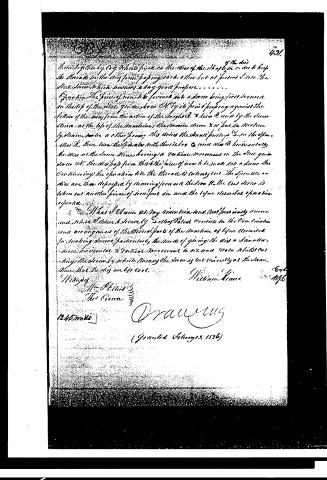
Page 4.
421.
the die is
thrust together by any means fixed on the axis of the shaft b in order to keep the threads in the die from popping back at this last of pressure I use the slice screw which answers a very good purpose.
Operation. The piece of iron to be formed into a screw being first secured in the top of the slide guide screw A. by its point pressing against the bottom of the way from the action of the weights B. & C. & D. and by the screw C. at the top of the machine, the machine screw X is put in motion by means, and in a short space this drives the small pulley B. on the spindle A. these turn the finals with their levers C. and the B. horizontally the dies at the same time having a vertical movement on the slide guide screw A. the die pops from this the piece of iron is made into a screw thus continuing the operation till the thread is entirely cut. The pieces are then disengaged by drawing forward the lever B. the cast screw is taken out another piece of iron put in and the before described operation repeated.
What I Claim as my invention and not previously known and which I claim securely by Letters Patent consists in the Combination and arrangement of the several parts of the machine as before described for making screws, particularly the mode of giving the die a Simultaneous horizontal & Vertical Movement to it and (to the shaft C) driving the screw by which means the screw is cut correctly at the same time that the dies are left cool.
Witnesses
William Keane
1245. m. 20
Drallweg
(Granted February 2, 1836)
DATAMP: illustration
Illustrations from DATAMP


DATAMP (Directory of American Tool and Machinery Patents), via the Internet Archive · Archived DATAMP page
About this record
- Patentee
- DATAMP
- Date
- the Name and Date index of patents, DATAMP, USPTO records
- Invention
- DATAMP
- Listed in
- the Name and Date index of patents, DATAMP, USPTO records, Jim Shaw's X-patent list, Burke's List of Patents (1847)
- Burke's 1847 Patent Office list gives the same patent.