

Drawings and documents
USPTO scan
The patent as scanned by the USPTO
-
 Page 1
-
 Page 2
-
 Page 3
-
 Page 4
-
 Page 5


U.S. Patent and Trademark Office · Google Patents
Show the transcription Hide (1,394 words)
Machine transcription (LightOnOCR) of the pages as scanned by the USPTO, most of them the handwritten copies made when the records were restored after the 1836 fire. Not checked; it can misread handwriting, so compare it with the scan.
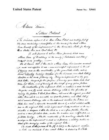
Page 2.
United States Patent
Patent No.: X9441
Abner Town.
Letters Patent.
The schedule referred to in this Letters Patent and making part of the same containing a description in the words of the said Abner Town himself of his improvement in the Eccentric Lathe for turning Gun Stocks, Shoe and Boot Laces &c.
To all persons to whom these presents shall come.
Abner Town of Woodbury in the county of Catawba and State of Vermont sends greeting.
Be it known that I the said Abner Town have invented, constructed and made and applied to use a new and useful improvement in the art of turning and in the construction of the gun stock lathe, called Town’s vibrating turning machine, (or the improved gun stock lathe) specified in the words following viz: Being an improvement on the gun stock lathe, designed for the purpose of turning gun stocks, laces, boot toes, hat blocks, and of turning to the shape of any given pattern.
The construction of the improved lathe or machine is such that both its guide and fly wheels remain stationary while in the operation of turning the pattern & block pass them; whereas in the original gun stock lathe, those wheels are movable and hold the pattern and block, both of which remain stationary; also in the improved machine the Pattern and block have each a separate mandrel turned by a wheel which is not the case in the original lathe. This improvement already mentioned in the construction is designed to hold the block in a more firm position, leave the work in a more finished state, render the machine more weightened, and facilitate turning. Also the construction of the machinery attached to the carriage in the improvement is such as to produce a rocking motion instead of the swinging motion of the original lathe.
The small hooks (added to the fly wheel) in the improved machine or lathe are designed to save great labour in preparing the blocks
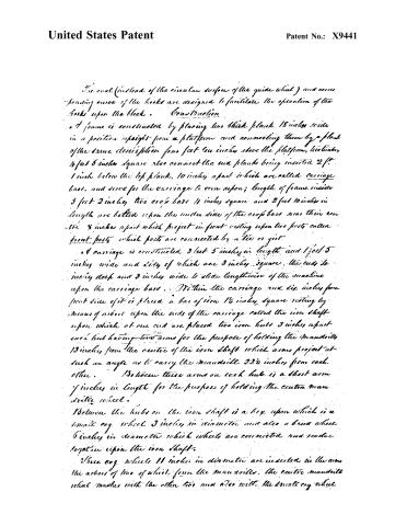
Page 3.
United States Patent
Patent No.: X9441
The oval (instead of the circular surface of the guide wheel) and corresponding curve of the hooks are designed to facilitate the operation of the hooks upon the block.
Construction
A frame is constructed by placing two thick planks 18 inches wide in a position upright from a platform and connecting them by a plank of the same description four feet ten inches above the platform, two timbers 4 feet 5 inches square also connect the end planks being inserted 2 ft. 1 inch below the top plank, 10 inches apart which are called carriage bars, and serve for the carriage to run upon; length of frame inside 3 feet 2 inches, two cross bars 4 inches square and 2 feet 10 inches in length are bolted upon the under side of the cross bars near their ends 8 inches apart which project in front resting upon two posts called front posts which posts are connected by a tie or girder.
A carriage is constructed 3 feet 5 inches in length and 1 foot 5 inches wide and 2 feet of which are 3 inches square, the ends 4 inches deep and 3 inches wide to slide lengthwise of the machine upon the carriage bars. Within the carriage and six inches from front side of it is placed a bar of iron 1½ inches square resting by means of arbor upon the ends of the carriage called the iron shaft upon which at one end are placed two iron hubs 3 inches apart each hub having two arms for the purpose of holding the mandrills 13 inches from the centre of the iron shaft which arms project at such an angle as to carry the mandrills 22½ inches from each other. Between these arms on each hub is a short arm 7 inches in length for the purpose of holding the centre mandrill wheel.
Between the hubs on the iron shaft is a box upon which is a small cog wheel 3 inches in diameter and also a brass wheel 6 inches in diameter which wheels are connected and rotate together upon the iron shaft.
Three cog wheels 11 inches in diameter are inserted in the arms the arbors of two of which form the mandrills, the centre mandrill wheel meshes with the other two and also with the small cog wheel.
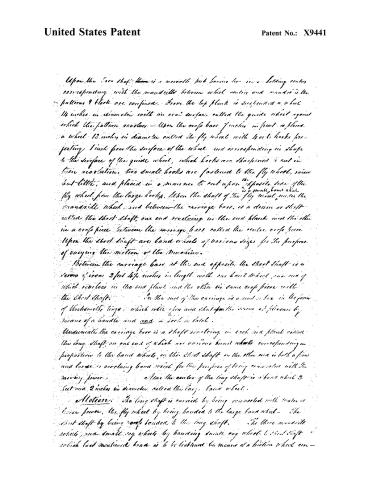
Page 4.
United States Patent
Patent No.: X9441
Upon the iron shaft there is a movable hub having two inner holding centers corresponding with the mandrels between which center and mandrel is the pattern & blocks are confined. From the top plank is suspended a wheel 14 inches in diameter with an oval surface called the guide wheel against which the pattern revolves—Upon the cross bars of the machine in front is placed a wheel 12 inches in diameter called the fly wheel with two hooks projecting 1 inch from the surface of the wheel and corresponding in shape to the surface of the guide wheel, which hooks are sharpened & cut in their revolution, two small hooks are fastened to the fly wheel, some but little, and placed in a manner to cut upon the opposite side of the fly wheel from the large hooks, when the shaft of the fly wheel meets the mandrel wheel and between the carriage bars is a drum or shaft called the short shaft, one end revolving in the end blocks and the other in a cross piece between the carriage bars called the center cross piece. Upon the short shaft are band wheels of various sizes for the purpose of varying the motion of the machine.
Between the carriage bars at the end opposite the short shaft is a screw of iron 2 feet 4½ inches in length with one band wheel, one end of which revolves in the end plank and the other in same cross piece with the short shaft. In the end of the carriage is a metal box in the form of blacksmith’s tongs, which with two arms that upon the screw of the same by means of a handle and one a hook & block.
Underneath the carriage bars is a shaft revolving in each end plank called the long shaft, on one end of which are various band wheels corresponding in proportion to the band wheels on the short shaft, on the other end is both a fixed and loose or revolving band wheel for the purpose of being connected with the moving power. Near the center of the long shaft is a band wheel 2 feet and 2 inches in diameter called the large band wheel.
Motion: The long shaft is carried by being connected with water or horse power, the fly wheel by being banded to the large band wheel—the short shaft by being rope banded to the long shaft. The three mandrel wheels and small cog wheels by banding small cog wheel to short shaft which last mentioned band is to be tightened by means of a friction wheel con-
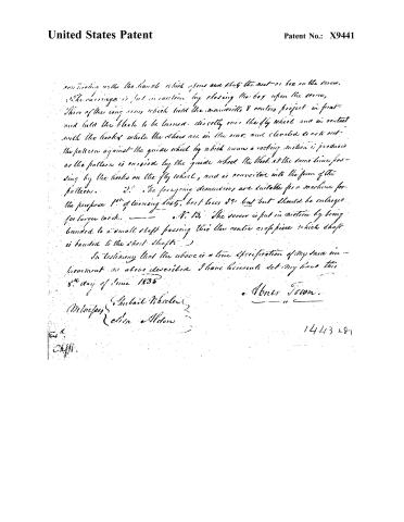
Page 5.
United States Patent
Patent No.: X9441
...with the hands which opens and shuts the nut or box on the screw. The carriage is put in motion by closing the box upon the screw. Three of the long pins which hold the mandrels & cutting project in front and hold the block to be turned, directly over the fly wheel and in contact with the hooks while the others are in the rear, and elevated to act as the pattern against the guide wheel by which means a rocking motion is produced as the pattern is carried by the guide wheel the block at the same time passing by the hooks on the fly wheel, and is converted into the form of the pattern.
2. The foregoing description are suitable for a machine for the purpose 1st of turning lugs, bolt holes &c. but but should be enlarged for larger work.
3. The screw is put in motion by being banded to a small shaft passing thro' the centre crosspiece which shaft is banded to the short shaft.
In testimony that the above is a true specification of my said invention as above described I have hereunto set my hand this 8th day of June 1835
Hubert Wheeler
Melrose
Elias Aldon
Homer Town.
1443 1.87
Published accounts: journal notice
Notice in the monthly list of patents, with remarks
Journal of the Franklin Institute, new ser., vol. 18 (1836), p. 254 · View the page
84. For an improved Lathe for turning Gun Stocks; Abner Town, Woodbury, Caledonia county, Vermont, February 25.
Remarks. We are informed that "the construction of the improved lathe or machine is such that both the guide and fly wheels remain stationary, while, in the operation of turning, the pattern and block pass them; whereas in the original gun stock lathe, those wheels are movable and pass the pattern, and block, both of which remain stationary. Also, in the improved machine the pattern and block have each a separate mandrill turned by a wheel, which is not the case in the original lathe. Also the machinery attached to the carriage in the improvement is such as to produce a rocking motion instead of the swinging motion of the original lathe, &c." We cannot attempt a verbal description of the differences pointed out in the foregoing abstract, which is to be considered as constituting the claim.
About this record
- Patentee
- DATAMP
- Date
- the Name and Date index of patents, DATAMP, USPTO records
- Invention
- DATAMP
- Listed in
- the Name and Date index of patents, DATAMP, USPTO records, Jim Shaw's X-patent list, the Journal of the Franklin Institute, Burke's List of Patents (1847)
- Burke's 1847 Patent Office list gives the same patent.