

Drawings and documents
National Archives restored drawings: drawing
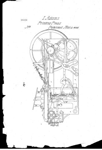
I Adams, Power Printing Press

National Archives, Restored Patent Drawings (Record Group 241) · Full-size scan at the National Archives · Catalog record
Show the text on the drawing Hide (54 words)
Words on the drawing as machine-read by the National Archives; not checked. Useful mainly for searching.
101. PRINTING, / ancelled. / Bed Printon mackines, / Roller inker, / Aissuea 13 June 1848. / I ADAMS / For Repun Crawmy / All 94 Large P.O / Power Printing Press / 94.C. / 9445-X / Patented 2ˢᵗ march 1836 / CLASSIFICATION / 94 / no / 9445X / 42 / 37 / 29 / 34 / 31 / 524 / 28 / 16 / 37 / OF 38 / >> / if / 10 / ML / N R / 39 / MAA / 14 / 2020 / 11 / I, / z,
USPTO scan
The patent as scanned by the USPTO
-
 Page 1
-
 Page 2
-
 Page 3
-
 Page 4
-
 Page 5
-
 Page 6
-
 Page 7
-
 Page 8
-
 Page 9
-
 Page 10
-
 Page 11
-
 Page 12
-
 Page 13
-
 Page 14
-
 Page 15


U.S. Patent and Trademark Office · Google Patents
Show the transcription Hide (5,669 words)
Machine transcription (LightOnOCR) of the pages as scanned by the USPTO, most of them the handwritten copies made when the records were restored after the 1836 fire. Not checked; it can misread handwriting, so compare it with the scan.
Page 1.
I. Adams.
Printing Press.
Patented Mar. 2, 1836.
9445X
No.
Fig. 1.
Page 2.
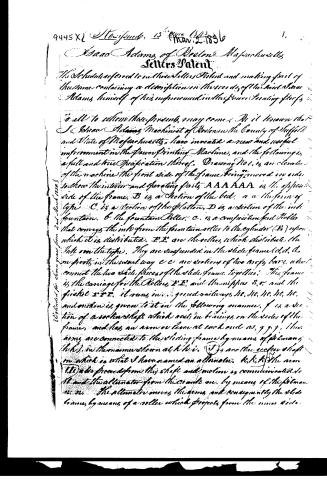
9445 X[ Steynede, 13th Mar. 1836 ] 1.
Isaac Adams of Boston Massachusetts
Letters Patent
The Schedules referred to in these Letters Patent and making part of the same containing a description in the words of the said Isaac Adams himself of his improvement in the Power Printing Press.
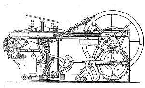
To all to whom these presents may come: Be it known that I Isaac Adams Machinist of Boston in the County of Suffolk and State of Massachusetts, have invented a new and useful improvement in the Power Printing Machine, and the following is a full and true Specification thereof. Drawing No 1, is an elevation of the machine the front side of the frame being moved in order to show the interior and operating parts. AAAAAAA is the opposite side of the frame. B is a Section of the bed. a a the form of type. C is a section of the platen. D is a section of the ink fountain. b the fountain Roller. c. is a composition feed Roller that conveys the ink from the fountain roller to the cylinder (B) upon which it is distributed. D.E. are the rollers which distribute the ink on the type. They are suspended in the slide frame (d,d) & m pivots in the usual way. c c are sections of two cross bars which connect the two side pieces of the slide frame together. This frame is the carriage for the Rollers D.E. and the nipples S.T. and the friction TTT. It runs in... ground railways, Hc. Hc. Hc. Hc. Hc. and motion is given to it in the following manner. f is a section of a socket shaft which rests in bearings on the sides of the frame, and has an arm or lever at each end as, g g g. These arms are connected to the sliding frame by means of pitman's links (h,h) in the manner shown at h h i i. J is another socket shaft on which is what I have named an alternator. k,k,k,k the arm. The arms proceed from this shaft and motion is communicated to it and the alternator from the crank on. by means of the pitman's links. The alternator moves the arms and consequently the slide frame, by means of a roller which projects from the inner side.
Entered for the Clerk of the Court of Patent for the United States 2nd March 1836
Page 3.
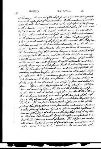
of the arm on the rear end of the shaft f, into a scrolled opening or groove in the upper part of the alternator. As the machine is now detailed, the roller last named would be in the upper part of the opening in the alternator; now it is quite evident that when the alternator begins to move, the roller together with the arms (g) and all attached to them will be moved by it, and the roller will descend in the opening until it arrives at O, where the opening begins to be on a circle with the shaft J. At this moment the slide frame will have arrived at the place where it must rest until the impression is given. The alternator however continues to move on, but the remaining part of the opening being on a circle with the shaft J, it merely lifts the roller and all attached to it from moving while the impression is being given. A completion of the revolution of the crank, or, well of course bring the alternator, and consequently the carriage or slide frame back to where they now are. Thus, by the means of the crank, and the alternator, the necessary reciprocating periodical movement is obtained for the press above described. G, G, is a stationary lymphan upon which the sheets to be printed are to be laid and printed. The lymphan is hung on pivots at g, to two standards, one arising from each side of the frame. After a sheet has been printed, it is taken from the lymphan, and carried in between the bed and the platter by a nipping on the bed v, which extends across from one side to the other of the slide frame. S, S, S, S, etc., is a notation of the two parts of the nipping jaws as they appear when open at the moment before they close to seize the sheet. The two parts (S S S S) of the nipping jaws are made of thin plates of thin plates of steel about four inches wide and are fastened to other pieces of steel on the rod v, which are fast together in the manner of the joint of a hinge on the pin that holds it together on the piece that the under lip of the nipping jaws are fastened to as projections (t) forming a sort of notch. The nipping jaws are continually drawn together by means of spiral springs, around around the rod v, one end of each being attached to the rod and the other
Page 4.
to the under half of the nipper. At one end of the rod (o) is a piece projecting at a right angle, from it, about two and a half inches long on the outside of this projection, near its end is a small roller which runs in a groove formed on the side of the frame for the purpose of operating the nippers. The manner of their operation is as follows. Suppose the machine to be in motion and the nippers (after an impression has been given) to be just emerging from under the platter. At this moment the roller on the end of the rod r enters the before named groove, which being arched, forces the roller downwardly and causes the rod r to turn. Also the upper half of the nipper being so fixed to the rod that they cannot turn on it, will be elevated as they are raised towards the tympan high enough to be sure to come on over the edge of the sheet of paper as it lays on the tympan. When they get near to the tympan they are made to descend by an edge hole or cradle in the groove above named until they come down hard on the sheet and the edge of the tympan which secures the sheet from moving from its place until the under halves of the nippers are brought up, and being thus rod r, which at this moment have but against projections on the frame and stopped but the slide frame continues to move on until the rollers t are disengaged which allows the under part of the nippers to be drawn up by the spiral springs against the upper parts. Then the sheet is seized by the nippers. H, H, is one of the two small cylinders one of which is secured by a pin through its end to each side of the slide frame within these cylinders are spiral springs and in their ends are pistons or slides (t) which are kept out by the springs. They enter the slots on which the rod r is placed and keep it firmly against the opposite parts, so when the rod is stopped by the projection as above named the pistons will be pressed into the cylinders and when the slide frame moves back the rod will be forced back into its place by the expansion of the springs. When it is necessary to take out the rod and nip
Page 5.
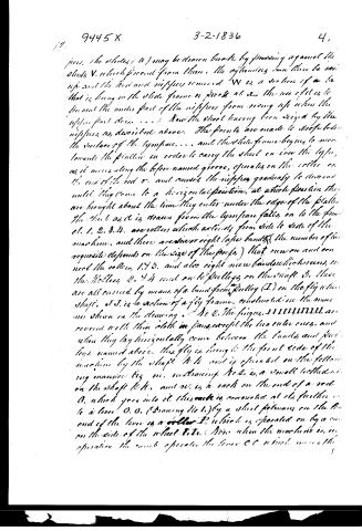
pieces. The slides (a) may be drawn back by pressing against the studs V, which proceed from them. The remaining can then be raised and the rods and nipples removed. W is a section of a bar that is hung on the slide frame or pivot at x. The use of it is to prevent the under part of the nipples from coming up when the upper part does. . . . Now the sheet having been seized by the nipples, as described above. The fronts are made to drop below the surface of the tympan. . . . and the slide frame begins to move towards the platter in order to carry the sheet on over the tops, as it moves along the before-named groove, operates on the roller on the end of the rod r, and causes the nipples gradually to descend until they come to a horizontal position, at which position they are brought about the time they enter under the edge of the platter. The sheet as it is drawn from the tympan falls on to the front et. 1, 2, 3, 4, are rollers which extend from side to side of the machine, and there are seven or eight tape bands (the number of the requisite depends on the size of the proofs) that run on and on near the rollers 1, 2, 3, and also eight more bands which cross, on the rollers 2, 3, 4, and on to pulleys on the shaft 5. These are all carried by means of a band from pulley (I) on the fly wheel shaft. At J is a section of a fly frame, constructed in the same manner shown in the drawing. At Q, the fingers, 1 1 1 1 1 1 1 1 …
Page 6.
9445 X 3-2-1836 5.
A.C. (Drawing No 2) which by means of the toothed wheel m. brings the flywheel to a horizontal position as shown in the drawing when it is held a short space of time until a quick turn or falling off in the cam b leaves the lever (O O) free, upon which a spiral spring (P Drawing No 2.) on the shaft R.R. causes it to turn and carry the flywheel on to the table that stands near by for the purpose. A continued movement of the cam b will turn the fly back, and so on alternately. M is a motion of a bellows which acts from side to side of the machine nearly but not quite. g.g. are two openings which extends the whole length of the bellows. The bellows is operated as follows. N is a shaft sustained in bearings on the sides of the machine. O.C. is one of two levers or arms, which extends out from the shaft under the bellows. P.P. is a lever on the same shaft with a Roller at its end that is operated on by the cam b Q. This Roller should now be in contact with the cam b, but I have drawn it in its present position in order to show the bellows to be represented open. R is another arm extending from the same shaft with the weight (S) suspended from its end. When the machine is in operation, the cam b operates the Roller on the end of the lever P.P. and raises the weight S and throws down the arm O.C. which allows the bellows to open but when the highest part of the cam b passes the roller the weight throws up the arms O.C. and closes the bellows and forces the wind out through the opening g.g. The object of the Roller, Pulleys, Tapes, Bands, and Bellows just described is to take the sheets of paper from the finisher after they have been printed, and lay them on a table prepared for the purpose. After a sheet has received an impression it is carried from under the platen on the finisher and papers along under the Tympian and Rollers I. K. at the moment the edge of the finisher has been carried as far as the Roller S. the highest part of the cam b Q will pass the roller on the lever P.P. which allows the weight S to operate the bellows and blow the air swiftly through the openings g.g. The current of air
Page 7.
have obtained strikes the under side of the sheet and carries its edge up against the laps on the Rollers 1. 3. The Rollers and Paper being in motion, and the sheet also continuing to advance with the first set, the edge of the sheet is quickly brought between the rollers 2. and the laps on the Rollers 1. 3. The sheet thus seized continues to be carried along on the laps that runs over the Rollers 2. 4. 11. and the pulleys on the shaft 5. until its edge strikes the upper edge of the main bar (6) or back bar of the fly, which takes place about the time that the most prominent part of the cam on the wheel L passes the roller on the lever O. C. which allows the spiral spring on the shaft 6. to throw the fly and lay the sheet on the table above named. The Bed is raised and the impression given in the following manner. TT is an alternator similar in principle to that described for giving motion to the first set frame. UU are the toggle joints, W. is a roller placed in a space for the purpose in the middle of the toggle joints, and on the pin in their center joint. The alternator is made to operate the toggle joints by means of the crank and pitman V Vm. Now suppose the machine to be situated as shown in the drawing. When it begins to move, the crank pin (m) on the cog wheel, will move in a downward direction, this by means of the two pitman, will carry the two alternators forward. RR will carry the arms g g. along until the first set is brought to the place where the impression must be given, but a little before the first set has stopped the point y on the alternator TT' will have come in contact with the Roller W. It may now be perceived that this part of the alternator forms an inclined plane in the side of a line of the second class, X being the fulcrum and that as it continues to advance the Roller W. will roll up on the inclined plane until the alternator has received of its motion in that direction at which time the toggle joints will have been forced up nearly to a perpendicular line which carries the type up firmly against the paper and platen and produces
Page 8.
the impression. A completion of a revolution of the crank and cog wheel, will of course bring all the parts to where they now are. S S is a section of what I term the bottom bar. It sustains the impression, and is connected to the platter by a two inch round bolt at each end. Z is a rocking shaft suspended in bearings to the two sides of the machine; it has two arms extending from it to W. From the end of each of these arms arises a rod X and connects with the bed; on each of these arms is placed a spiral spring A A to assist in raising the bed. Z Z is one of two levers that the pin 10 passes through, to connect the leg joints to the bed. These levers are connected at 11 to a bar 12 that rests on the spiral springs A A. 13, 13, are sections of a wedge and lever, by means of which the impression is increased or diminished. The Bed is kept steady in rising and falling by means of a guide (14) at each end of the bed which runs in grooves on the inner sides of the frame, and also by the two rods X which keep it from leaning endwise. The ink is distributed in the usual way viz by rolling together the Roller and cylinder. The cylinder is carried by a band from a pulley on the fly wheel shaft to a pulley (16) on the shaft of the cylinder. 17, 17, is a short roller which distributes the ink laterally on the cylinder; it is connected to a small frame or carriage 18, 18, which runs in rods 19, 19; it is made to travel by being placed obliquely against the cylinder. 20, 20 is a weight and lever connected to the short spindle 21. This spindle has a cross piece on its end from one end of which arises the rod (22) and connects with the little frame 23, which the Roller runs in. This last named frame is connected to the carriage (18, 18) by a spindle. Now when the Roller has arrived at one end of the cylinder a projection from the lower part of the scroll which sustains the rods 19, 19, comes in contact with the lever 20 (and the Roller continuing to advance, turns it in the opposite direction. This by means of the little connecting rod
Page 9.
(2.2) overcomes the obliquity of the Roller which causes it to commence its journey the other way, and so on alternately. The fountain is constructed in the usual way excepting that the quantity of water is regulated by means of a rod that runs the whole length of the fountain, and is made wedging at each end, the pieces which forms the bearings for the fountain Roller, bear against those parts of the Rods which are wedging, so that moving the Rod one way or the other enlarges or keeps the space between the Rollers and surface for the water to flow through. The wedge is moved by means of a screw which screws into a little stud on the rod, and is attached to a similar stud on the fountain. Another way I have is to use a round rod made eccentric at each end where the pieces forming the bearings of the fountain Rollers come against it. This rod is placed in firm bearings on the sides of the fountain, and holes are made through one end of it so that by means of a small lever it may be moved on its axis, which has the same effect as moving the edge inward. The pivots or guide pins of the Rollers which distribute the water over the type are put into smooth holes in the ends of the Rollers, and are kept out by means of springs put inside of the Rollers. The object of this is that the guide pins may be pressed into the body of the Rollers, and consequently be drawn out of the holes that form their bearings so that the rollers may be handily removed from their places without having movable caps over their bearings; another way to construct the riffles is, see at figures 14.2, drawing No 2. a. a. a Fig 1 is a frame suspended to the spoked frame by the pivots b. b. to this is fixed another frame c. c. d the ends c. c. of which are fitted in grooves in the ends of the frame a. a. a. The frame c. c. d. is kept out in its present place by a spring c. c. Fig 2. is a section of the frames above named with or with the riffles f. The riffles are secured to the side (d Fig 1.) of the frame c. c. d. by means of screws g. Fig 2. The riffles are closed by means of the Rod h. in the following manner. The Rod is secured to the frame d. by means of pins or screws (k) which pass through slots made in a diagonal direction through it, and its end i is fitted to the end pieces of the frame a. a. a. in the manner of a nut.
Page 10.
Now first before the upper parts of the nippers are brought on the edge of the sheet of paper and tympan as described of the nippers before named, the lower part of the frame aed is brought against projections on the sides of the machine which sloped, but the other frame a a a continues to move, consequently its end piece at e is made to operate in the manner of a wedge against the end of the Rod b which slips along on the frame d and the slots being diagonal as above named, rises up also, and closes the nippers on the sheet. When the sheet has been carried nearly to the place where it is to receive the impression as above described, the end of the Rod b is brought against an inclined plane which forces it back and leave the nippers free to open again. A is a roller on the frame a a a by means of which the nippers are operated in the manner described of the first named nippers.
The tympan is a frame of wood covered with sheet iron on its upper side as far down as 24-25. 24. are two small holes made in the end piece, at the further end of the tympan, these are for the purpose of receiving the end of the Rod, which it is necessary to put across from end to end of the tympan. When the paper is broad in order to keep its edge from bending down. The rear end of the rod is kept in its place by passing a pin through the end piece of the tympan into a hole drilled for that purpose in the end of the Rod. The pin is made so as to be easily drawn out with the fingers, so that the rod may be quickly shifted from one place to the other. The pieces on the tympan that are colored yellow in the drawing are secured in their places by means of the little bolts and nuts 27. 28. 29. 30. Points 31. 31. are fixed through little projections, on their ends and are caused to project beyond the face of the tympan... and to fall back (to as to allow the sheet to be drawn off) by means of the little levers 32. 32. The ends of these levers come together and are attached to the ends of another lever 33. 33. at the centre of the tympan 34. This last named lever runs diagonally from the centre of the tympan about seven or eight inches, it then turns and runs in a direction perpendicular of the machine until it reaches the further part of the tympan. If then...
Page 11.
angles in the direction 33, 33, it is operated as follows. On the slide frame is a little comb, so situated that when the slide frame moves, along the comb comes under the end of the lever and raises it up, which thrusts the points out as they are shown in the drawing, and on the side of the machine is fixed a spring, that will when the end of the lever is raised as above named spring out under it and hold it up. Now when the time comes for the points to be drawn in, another little comb on the side of the slide frame presses off the spring and disengage the lever, which will then by its own weight drop down, and draw in the points. It is sometimes necessary that the points should be placed so as to range in the each other lengthwise of the sheet and sometimes otherwise. It is therefore necessary that the points should be so fixed that their situation may be easily changed, for this purpose there are two circular slots cut in the face of the tympan, the common centre of which is the screw or pin which connects the two levers that operate the points to the end of the lever 33, 33. The bolts 27, 29, are put through these slots so that by loosening the nuts on them the pieces to which the points are attached may be moved round and secured at any point that may be requisite. The upper half of the nippers, are a little longer than the lower halves, so that their ends may reach on to the edge of the tympan (or the rod before named to confine the sheet before the under half fly up. There must be a number of pairs of nippers, of nippers of different lengths on account of the forms of type being of various widths. 35, V 36, are sections of the two parts of the parchment tympan frame, this is secured by two slide bolts, in the platen near 36. - 37, 38 are rollers to which the tympan sheet is secured. a long sheet is procured for this purpose (it may be made by pasting common sheets together) and rolled up on one of the rollers, its end is then passed under the platen, and secured to the other roller, which is turned until the sheet is drawn smooth under the face of the platen. Both rollers are then drawn from turning by galls being fastened into a solid sheet on the end of each roller. The ends of the sheet are secured to their rollers by
Page 12.
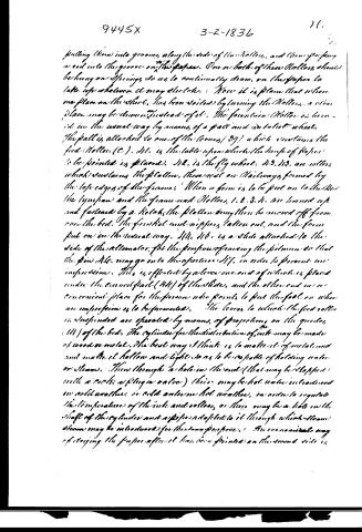
putting them into grooves, along the side of the rollers, and then pressing a rod into the grooves on the paper. One or both of these rollers should be hung on springs, so as to continually draw on the paper to take up whatever it may dislocate. Now it is plain that when one place on the sheet has been spoiled by burning the rollers, a clean place may be chosen instead of it. The fountain roller is turned in the usual way by means of a pallet and a toothed wheel. The pallet is attached to one of the levers (B) which sustains the feed roller (C). D is the table upon which the sheet of paper is to be printed in place. E is the fly wheel. F, G, H, I are rollers which sustain the platen, there are on railways formed by the top edges of the frames. When a form is to be put on to the bed the tympan and the frame and rollers, 1, 2, 3, 4, are turned up and fastened by a hook, the platen may then be moved off from over the bed. The fountain and nipping taken out, and the form put on in the usual way. M, N is a slide attached to the side of the alternator, for the purpose of raising the platen so that the pin A may go into the aperture S, in order to prevent an impression. This is effected by a lever one end of which is placed under the curved part (H) of the slide, and the other end in a convenient place for the person who prints to put the foot on when an impression is to be prevented. The levers to which the feed roller is suspended are operated by means of projections on the guides (M) of the bed. The cylinder for the distribution of ink may be made of wood or metal. The best way I think is to make it of metal, and not make it hollow and light, so as to be capable of holding water or steam. Then through a hole in the end (that may be stopped with a cork, a plug or valve) there may be hot water introduced in cold weather, or cold water in hot weather, in order to regulate the temperature of the ink and rollers, or there may be a hole in the shaft of the cylinder and a pipe adapted to it through which steam alone may be introduced for the same purpose. An economical way of drying the paper after it has been printed on the second side is
Page 13.
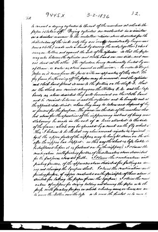
to connect a drying cylinder to the end of the machine at which the paper is taken off. Drying cylinders are constructed in a similar or a similar manner to the metallic rollers above described for the distribution of the ink; only they are made considerably larger and have a cloth (made into a band by sewing the ends together) which runs on rollers, and against the side of the cylinder so that the paper may enter between the cylinder and cloth band on one side, and come out dried at the other. The cylinder, being continually heated by means of steam, or water as above named or otherwise. In order to dry the paper as it comes from the press with an apparatus of this sort, the fly frame for throwing off the paper may be removed, and the cylinder and cloth band placed so near to the rollers on the shaft D, that as the sheets are carried along over the rollers D, H, and the tape bands, as above described, they will be received on the cloth band and be carried between it and the cylinder and be brought out at the opposite side dried, where they may be taken and disposed of by a person for the purpose. The groove on the side of the machine described above for the operation of the nippress may instead of being made stationary be made in the end of a lever attached to the side of the frame, which may be operated by a cam on the fly wheel. This I believe to be the best way when accurate regulation is required; yet the upper parts of the nippress may be brought down on the shaft after the nippress has stopped, in this way the sheet is less liable to be displaced before it is fastened on by the nippress. I claim the combination with printing presses of the rollers above described for the purposes above set forth. I claim the combination with printing presses, of the apparatus above described for fastening, securing and changing the typeform sheet. I claim the combination with printing presses, of nippress constructed on the principle of those above described for taking the paper from the typeform. I claim the combination of nippress for drying, holding and drawing the paper into the press, with printing presses in which vibrating arms or levers are used to move the rollers over the type or to move the finisher or to move the
Page 14.
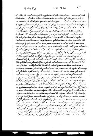
I claim the combination of the nippers with the slide frame instead of with the friskets. I claim the combination above described of those parts which are essential to the proper operation of the nippers. I claim the combination of nippers for dividing the paper into the proofs as above described with springing presses in which the ink is distributed on the rollers, that distribute it over the types, by means of cylinders or rollers instead of tables or plane surfaces. I claim the combination of wedges and also of eccentricity with the ink fountain for altering the space between the roller and scraper. I claim the combination above described of those parts which constitute the stationary type and the various parts connected with it which are essential to the operation of the forms and to facilitate the taking of the sheet by the nippers. I claim the combination of vibrating arms or levers for moving the rollers over the forms, for moving the frisket, or for moving both rollers and frisket, with printing presses in which a crank is used to operate the log joints which produce the impressions. I claim the combination of stationary points (that is points which never come between the bed and platen) with printing presses in which vibrating arms or levers which move vertically are used for moving the rollers that pass over the types, for moving the frisket or for moving them both. I claim the combination of a crank which moves vertically to operate the log joints which produce the impressions with printing presses in which the rollers are passed between the bed and platen to ink the types. I claim the combination of the wedge for altering the impression with the bed instead of the bottom bar. I claim various apparatuses of various kinds may be used for raising the sheet from the frisket as above described, as for instance, the Belouy the air pumps or the vibrating or revolving fans, and these may be used to raise the sheet by drawing air into holes just over the sheet of paper, or they be used as above described to force the sheet up by producing a current of air against the under side. I claim the combination of the pneumatic apparatus with printing presses for raising the sheet of paper from the frisket. I claim the combination of rollers as above described and bands and fixtures with printing presses for removing the sheet from the frisket. I claim the combination of the fly frame with the rollers and with the
Page 15.
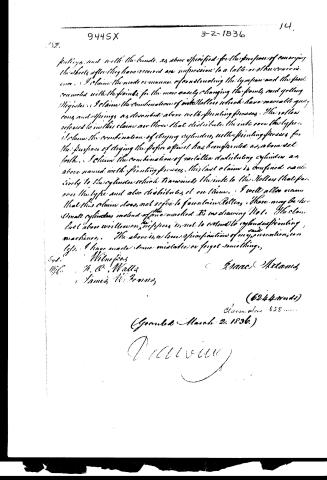
picking, and with the bands, as above specified, for the purpose of conveying the sheets after they have received an impression to a table or other convenience. I claim the mode or manner of constructing the tympan and the feed connected with the points, for the more easily changing the points and getting registers. I claim the combination of ink rollers which have movable gears, cones, and springs, as described above, with printing presses. The rollers referred to in this claim are those that distribute the ink over the type. I claim the combination of drying cylinders, with printing presses, for the purpose of drying the paper after it has been printed, as above set forth. I claim the combination of metallic distributing cylinders, as above named, with printing presses. This last claim is confined exclusively to the cylinders which transmit the ink to the rollers that pass over the type and also distribute it on them. I will also claim that this claim does not refer to fountain rollers. There may be two small cylinders instead of one marked D in drawing No. 1. The claim last above written on the reverse is not to extend to cylinder printing machines. The above is a true specification of my invention, to the best of my knowledge. I have made some mistakes or forgot something.
Test.
1836.
Witnesses:
H. A. Wells
James W. Brown
Emac Atkins
(6244 words)
Claim alone 658 words
(Granted March 2, 1836.)
Patented
Published accounts: journal notice
Notice in the monthly list of patents
Journal of the Franklin Institute, new ser., vol. 17 (1836), p. 437 · View the page
142. Power Printing Press. Isaac Adams, Boston, Mass.
Published accounts: journal notice
Notice in the monthly list of patents, with remarks
Journal of the Franklin Institute, new ser., vol. 18 (1836), p. 313 · View the page
2. For a Power Printing Press; Isaac Adams, city of Boston, Massachusetts, March 2.
Remarks. We cannot attempt to give any description of this press, the specification of which occupies sixteen pages, with numerous references to the drawings; the claims amount to twenty-one in number, and it will be a fortunate, and very remarkable, circumstance, should the whole of them prove tenable. The press has been tried, and we are informed that it operates well, and is much superior to that patented by the same gentleman, which was itself a good one. The combinations in the present instance are sufficiently novel and characteristic to render it unnecessary to resort to minute particulars in the claims, a course which is commonly pregnant with danger; if one thing only that is essential to the existence of a machine is claimed, it is safe to trust to this alone. In the case before us, we could point out more than one thing claimed which is not new, and the patentee himself informs us respecting one of them, that "the claim last above written, on the nippers, is not to extend to cylinder printing machines;" a court and jury, we apprehend, would not regard such a limitation.
DATAMP: illustration
Illustrations from DATAMP

DATAMP (Directory of American Tool and Machinery Patents), via the Internet Archive · Archived DATAMP page
About this record
- Patentee
- DATAMP
- Date
- the Name and Date index of patents, DATAMP, USPTO records
- Invention
- DATAMP
- Listed in
- the Name and Date index of patents, DATAMP, USPTO records, Jim Shaw's X-patent list, the Journal of the Franklin Institute, Burke's List of Patents (1847)
- Burke's 1847 Patent Office list gives the same patent.