

Drawings and documents
USPTO scan
The patent as scanned by the USPTO
-
 Page 1
-
 Page 2
-
 Page 3
-
 Page 4
-
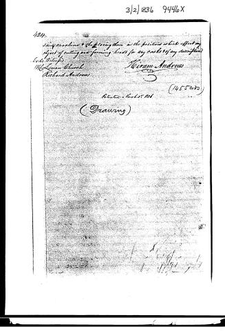 Page 5


U.S. Patent and Trademark Office · Google Patents
Show the transcription Hide (1,355 words)
Machine transcription (LightOnOCR) of the pages as scanned by the USPTO, most of them the handwritten copies made when the records were restored after the 1836 fire. Not checked; it can misread handwriting, so compare it with the scan.
Page 1.
9446X
H. Andrews,
Making Barrel Heads,
Patented Mar. 2, 1836.

A.M. PHOTO-LITHO. CO. N.Y. (OSBORNE'S PROCESS)
Page 2.
3/2/1836 9446X
March 2 1836 421.
Heiram Andrews of Canaan, County of Litchfield, Connecticut.
The schedule referred to in this Letters Patent and making part of, the same containing a description in the words of the said Heiram Andrews himself of his improvement in the machine for making Headings of casks barrels &c
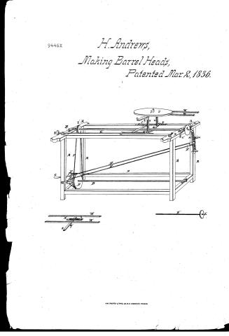
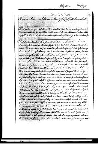
To all People to whom these presents shall come. Be it known that I Heiram Andrews of Canaan in the County of Litchfield & State of Connecticut have invented a new and useful machine for the purpose of cutting & forming heads or heading for barrels & other casks & that the following is a full and exact description thereof. First an upright frame of any convenient size generally in the form of a parallelogram & composed of any substantial material as iron wood or otherwise, upon the lower pieces of the frame is placed a revolving horizontal shaft of iron wood or other substantial material on the one end of which is affixed a crank by which the machine may be propelled or if it is required to propel the same by water or other power the crank or handle aforesaid may be removed and any other proper machinery may be attached to accomplish this object. Upon one end of this shaft is affixed a whorl or drum over which revolves a strap connected with two revolving pulleys directly opposite and attached to the opposite side of the frame by means of a shackle. On the top of the frame in the centre thereof is placed another horizontal shaft in the same direction with the other & leaving on the upper parts of the frame on the one end of this shaft is also a whorl connected by a strap with a whorl or drum on the one of the first mentioned shaft on the other end of this second shaft are affixed by means of a screw nut or in any other firm manner two circular saws with no interval between them, the outside saw is the largest of the two & is concave convex & saws the inside level of the heading the concavity of this saw is formed by the arc of a circle about one seventh larger than the heading required, this saw formed to cut heading seventeen inches in diameter will vary so as to
Page 3.
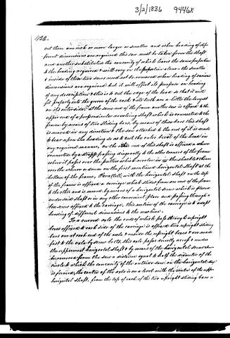
cut them one inch or more larger or smaller and when heading of different dimensions are required this saw must be taken from the shaft and another substituted the concavity of which leaves the same proportion to the heading required & will vary in the proportion alone—the smaller & inside of these two saws need not be removed when heading of various dimensions are required but it will effect its purpose on heading of any description & this is to cut the edge of the head so that it will fit properly into the groove of the cast & its teeth are a little the longest on its outer side; at the same end of the frame another saw is affixed to the upper end of a perpendicular revolving shaft which is connected to the frame by means of two sliding bars, by means of these bars this shaft is moved in any direction & the saw attached to the end of it is made to bear upon the heading so as to cut the outer bevel of the head in any required manner, on the other end of this shaft is affixed a whurr connected by a strap passing diagonally to the other corners of the frame where it passes over the pulleys which revolves in in the shackle & thence over the whurr or drum on the first mentioned horizontal shaft at the bottom of the frame, Parallels with the horizontal shaft on the top of the frame is affixed a carriage which slides from one end of the frame to the other and is moved by means of a horizontal screw which is placed under said shaft or in any other convenient place and passing through a box screw affixed to the carriage, this motion of the carriage is to adapt heading of different dimensions to the machine.
To a curved axle, the ends of which pass through upright boxes affixed to each side of the carriage is affixed two upright sliding bars one at each end of the axle & inside the upright boxes & are made fast to the axle by screw bolts, this axle passes directly across & under the uppermost horizontal shaft & by means of the horizontal screws there be removed from the saw a distance equal to half the diameter of the circle to which the concavity of the outside saw on the horizontal shaft is formed, the centre of the axle is on a level with the centre of the upper horizontal shaft, from the top of each of the two upright sliding bars a
Page 4.
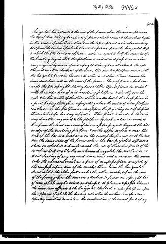
Horizontal bar extends to the end of the frame where the saws are placed on the top of this sliding bars, is a crof piece which connects them together in the centre of which is a slide & on the top is placed a circular revolving platform the centre of which should be placed from the horizontal shaft to which the two saws are affixed a distance equal to half the diameter of the heading required & this platform is raised or depressed as occasion may require by means of said upright sliding bars attached to the axle this motion alters the level of the head, this circular platform moves with the horizontal bars & in the same direction and when turned toward the saws said bars rest on the end of the frame, the crof piece which connects the two upright sliding bars at their top, is placed in contact with the under side of said revolving platform & directly over the axle & in the centre of the slide which is attached to this crof piece is a pivot passing through, and projecting above the centre of said platform on the same, the platform revolves upon the projecting end of the pivot this material for heading is fixed. This pivot is made to slide in any direction required & the platform by such motion is carried to or from the saws one end of said crof bar projects beyond the side or edge of the revolving platform & on the upper surface & near the end of the bar is a mash and on the end of the frame next the saw on the same side of the frame where the bar projects is affixed a slide on which is a similar mash the use of these two parts of the machine is to enable the workman to regulate the machine so as to cut heading of any required dimensions and is done in this manner, take the admeasurement in a pair of compasses place one foot of the compass upon one of the mashes then turn the horizontal screw until the other foot reaches the other mash, upon the end of the frame where the saws are attached is fixed an upright bar of iron which may be raised or depressed at pleasure & passes between the inner saw affixed to the horizontal shaft & the circular platform upon the upper one of which the heading rests when the machine is in operation. Upon my invention consists in the combination of the several parts of my
Page 5.
124.
Said machine & the placing them in the positions which effect my object of cutting and forming heads for any casks of any description.
Evds Wilkins
1196 Leman Church
Richard Andrews
Hiram Andrews
(1455 words)
Patented March 29, 1836
(Drawing)
Published accounts: journal notice
Notice in the monthly list of patents
Journal of the Franklin Institute, new ser., vol. 17 (1836), p. 437 · View the page
147. Cask and Barrel Headings.-Hiram Andrews, Canaan, Conn.
Published accounts: journal notice
Notice in the monthly list of patents, with remarks
Journal of the Franklin Institute, new ser., vol. 18 (1836), p. 314 · View the page
7. For Cutting and forming heads for barrels, &c.; Hiram Andrews, Canaan, Litchfield county, Connecticut, March 2.
Remarks. Various machines are in use for cutting heading for casks, &c., but that described in the specification of this patent appears to be sufficiently new to justify a claim to invention. The heading is to be cut rounding by means of a concave, circular saw on a revolving shaft, within which saw there is a circular cutter, of somewhat less diameter than the saw, and in contact with it, furnished with teeth so formed as to give the proper bevel to one side of the head. A similar cutter on another shaft bevels the opposite side of the head, the latter being properly secured on a revolving platform, operating as a chuck. The drawing is very indifferently executed, affording but a general idea of the machinery, and is, therefore, not such as the law requires. The specification affords a good general description, but no more; and the claim is to "the combination of the several parts of the machine, and the placing them in the position which effects the object of cutting and forming heads for any casks of any dimensions." Such a claim we do not think good, as it does not designate any particular combinations, as characteristic of the machine, whilst several of the things combined, have been similarly arranged in other machines, for the same, or other purposes.
DATAMP: illustration
Illustrations from DATAMP

DATAMP (Directory of American Tool and Machinery Patents), via the Internet Archive · Archived DATAMP page
About this record
- Patentee
- DATAMP
- Date
- the Name and Date index of patents, DATAMP, USPTO records
- Invention
- DATAMP
- Listed in
- the Name and Date index of patents, DATAMP, USPTO records, Jim Shaw's X-patent list, the Journal of the Franklin Institute, Burke's List of Patents (1847)
- Burke's 1847 Patent Office list gives the same patent.