

Drawings and documents
National Archives restored drawings: drawing
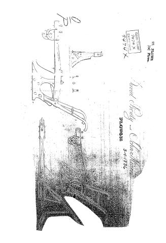
David Prouty and John Mears' Patent Drawing for a Plough

National Archives, Restored Patent Drawings (Record Group 241) · Full-size scan at the National Archives · Catalog record
Show the text on the drawing Hide (21 words)
Words on the drawing as machine-read by the National Archives; not checked. Useful mainly for searching.
7/8 / is / 2000 / Line of / Section / player
USPTO scan
The patent as scanned by the USPTO
-
 Page 1
-
 Page 2
-
 Page 3
-
 Page 4


U.S. Patent and Trademark Office · Google Patents
Show the transcription Hide (1,055 words)
Machine transcription (LightOnOCR) of the pages as scanned by the USPTO, most of them the handwritten copies made when the records were restored after the 1836 fire. Not checked; it can misread handwriting, so compare it with the scan.
Page 1.
97. PLOWE.
[114] PLOWE.
CLASSIFICATION:
9474 X
DIVISION:
9474 X
David Chudy and Chucky
PLOWE
3-4-1836
Page 2.
3/4/1836 9474 X
March 4, 1836 427
David Procty & John Means.
Letters Patent
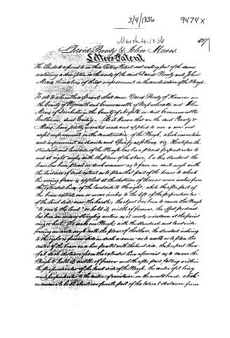
The Subjects referred to in their Letters Patent and making part of the same, containing a description in the words of the said David Procty and John Means themselves of their improvement in the construction of the Plough.
To all to whom these presents shall come, David Procty of Haverhill in the County of Plymouth and Commonwealth of Massachusetts, and John Means of Dorchester in the County of Norfolk in said Commonwealth Gentlemen, and Greeting. — We do know that we the said Procty & Means, have jointly invented, made and applied to use a new and useful improvement in the construction of the Plough, which invention and improvement we describe and specify as follows, viz. Wherefore the standard and landside of the Plough has been placed perpendicular to and at right angles with the plane of the share. On this standard the beam has been placed in such manner as to form an acute angle with the landside of such extent as to place that part of the beam to which the moving plow is applied at the distance of three or more inches from the extended line of the landside to the right, while the after part of the beam extends one or more inches to the left of the perpendicular of the landside near the handle; the object has been to cause the Plough “to run to the land” or hold its width of furrow. The effect produced has been an easy tugging motion as it meets resistance at the point wing or heel. We make our Ploughs with the standard and landside forming an acute angle with the plane of the share, the standard inclining to the right or furrow side in such manner as to enable us to place the center of the beam one line parallel with the landside, the fore part there of at such distance from the extended line of the same as to cause the Plough to hold its width of furrow and the after part falling within the perpendicular of the landside of the Plough, the center of it being nearly perpendicular to the center of resistance on the mould board, which resistance is to be about one fourth part of the lateral distance from
Page 3.
3/4/1836 9474X
1/38.
the,
Landside the wing of the share, and at about one third part of the perpendicular height from the plane of the share to the upper edge of the mouldboard. This location of the centre of resistance, we base on the fact that many Ploughs which have been used in sharp steady soils have been worn quite through at that point. The result of this formation of the plough, is a steady well balanced motion requiring less power of draft, and less effort in directing the Plough in its course.
The inclination of the standard and landside causes the Plough to cut under and take up the furrow in the form of an oblique angled parallelogram, or like a board featheredged, which being turned over falls in level with the last furrow more readily than the right angled or squared edged work. The coulter or knife having a similar inclination cuts the roots of the grass &c. and leaves all vegetable matter on the surface at a greater distance from the under edge of the furrow which being turned over more readily falls in and is far better covered than with squared edged work. The top of the standard through which the bolt passes to secure the beam is transversely parallel to the plane of the share, and extends back from the bolt to such distance as to form a brace to the beam, when the after part is pressed down by lifting at the fore part the share being fast under a rock or other obstruction. The after part of this extension is squared in such manner that being jugged into the beam it secures the bolt in heavy drafts.
The bolts which are used to fasten the pieces of cast iron (of which our ploughs are made) together and to the iron work are secured with inverted cross heads, or like the wood screws, with a projection on the under side of the head of a similar form which fits into a groove in the corresponding part of the bolt hole as it is cast to receive it, which not only prevents its turning but also diminishes the liability of breakage at the corners of square holes all which will more fully appear by reference to the drawing annexed to and forming part of this specification. We hereby declare that what we claim as new of our invention is the construction of such Plough as aforesaid
Page 4.
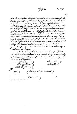
3/4/1836 9474x
and the several parts thereof not separately, but in combination for the purpose aforesaid. viz 1st The inclining the Standard and Land side so as to form an acute angle with the plane of the Share. 2nd The placing the beam on a line parallel to the land side, within the body of the Plough, and its centre nearly in the perpendicular of the centre of Resistance. 3rd The forming the top of the Standard for Brace and draft. We do not confine our claim to any particular form or construction excepting such form as may be necessary to place the beam in the perpendicular of the centre of resistance and parallel to the land side and also to such form of the top of the Standard as shall serve for brace and draft but have given such forms as we deem to be most convenient which may be varied as is obvious.
In testimony that the above is a true specification of our invention we have here to set our hand this 4th day of November in the year of our Lord one thousand eight hundred and thirty-five
Witnesses
George Beatty
Ellis Hay Soring
David Beatty
John Morris
Pat. No. 406 and (Filed 4th March 1836.)
Graves
Published accounts: journal notice
Notice in the monthly list of patents
Journal of the Franklin Institute, new ser., vol. 17 (1836), p. 438 · View the page
172. Plough.-D. Prouty and J. Means, Boston, Mass.
Published accounts: journal notice
Notice in the monthly list of patents, with remarks
Journal of the Franklin Institute, new ser., vol. 18 (1836), p. 321 · View the page
32. For an improvement in the Plough; David Prouty, and John Mears, Boston, Massachusetts, March 4.
Remarks. The claims made consist, "First, in the inclining the land side, so as to form an acute angle with the plane of the shear. Second, the placing the beam on a line parallel to the land side, within the body of the plough, and its centre nearly in the perpendicular of the centre of resistance. Third, the forming of the top of the standard for brace and draught." These points, it is stated, are not claimed separately, but in combination with each other. This plough, we are informed, has been highly approved by those farmers who have used it.
DATAMP: illustration
Illustrations from DATAMP
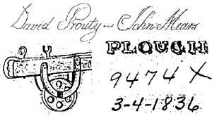

DATAMP (Directory of American Tool and Machinery Patents), via the Internet Archive · Archived DATAMP page
About this record
- Patentee
- DATAMP
- Date
- the Name and Date index of patents, DATAMP, USPTO records
- Invention
- DATAMP
- Listed in
- the Name and Date index of patents, DATAMP, USPTO records, Jim Shaw's X-patent list, the Journal of the Franklin Institute, Burke's List of Patents (1847)
- Burke's 1847 Patent Office list gives the same patent.