

Drawings and documents
National Archives restored drawings: drawing
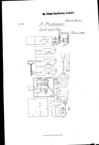
August Pruetzmann's Patent Drawing for an Improved Lever Key and Lock


National Archives, Restored Patent Drawings (Record Group 241) · Full-size scan at the National Archives · Catalog record
Show the text on the drawing Hide (61 words)
Words on the drawing as machine-read by the National Archives; not checked. Useful mainly for searching.
Sheet 1. 70. / classification / AUC WST / 9475, X / Impd Lever Key and Lock. / Patented March 4th 1836 / DIVISION / N: 2. / og / 6a / By / in / 10 / to / at / Act
Sheet 2. 9475 X / V#6 A. a PRUTZMANN' $ impd Liever Key and Lock: N.1. / CLASSIFICATION / Patented March 4th 1836 / GL / tan / Exp / of / RR / LT / JC
USPTO scan
The patent as scanned by the USPTO
-
 Page 1
-
 Page 2
-
 Page 3
-
 Page 4
-
 Page 5
-
 Page 6
-
 Page 7


U.S. Patent and Trademark Office · Google Patents
Show the transcription Hide (2,047 words)
Machine transcription (LightOnOCR) of the pages as scanned by the USPTO, most of them the handwritten copies made when the records were restored after the 1836 fire. Not checked; it can misread handwriting, so compare it with the scan.
Page 1.
No Printed Specification Available
9475X
A. Prutzmann,
Lock and Key.
Patented Mar. 4, 1896.
2 Sheets-Sheet 1.
AM. PHOTO-LITHO. CO. N.Y. (OSBORNE'S PROCESS)
Page 2.
No Printed Specification Available
2 Sheets—Sheet 2.
9475X A. Prutzmann,
Lock and Key.
Patented Mar. 4, 1886.
AM. PHOTO-LITHO. CO. N.Y. (OSBORNE'S PROCESS)
Page 3.
Mar. 4, 1836
Augustus Prutzmann.
Letters Patent.
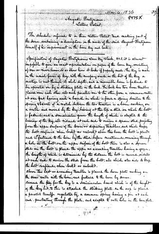
The Schedule referred to in these Letters Patent and making part of the same, containing a description in the words of the said August Prutzmann himself of his improvement in the lever key and lock.
Specification of Augustus Prutzmann's Lever Key & Lock, No. 1. It is almost impossible to give an exact representation on paper of the lever key, consisting of one or more levers, so as to show how it locks if properly made. The key is made in the usual form of key, with the necessary wards. In the bit of the key a mortice is cut through its whole depth, and a moveable lever is fastened to be operated on by a striking plate in the lock. The lock has two lever tumblers placed one over each other and work parallel one to the other, from a common centre. At one end having each a barrel in which is fixed a spring similar to the spring barrel of a match. Between the two tumblers is a lever working on a centre and moved by the key, having at the top a stud on which the bolt is fastened, and a semicircular groove the length of which is adapted to the leverage of the key, and widened at each end to receive a square stud, projecting from the upper surface of the lower or depending tumbler, and which keeps the bolt confined when locked or unlocked. Above this lever the bolt is placed and is fastened to the lever by the stud before mentioned, running through a hole in the bolt. On the upper surface of the bolt there is also a square stud on the bolt is placed the upper or ascending tumbler having a groove, the length of which is determined by the distance the bolt is moved, widened at each end to receive the stud from the bolt, and which also aids to keep the bolt confined, when locked or unlocked.
Above this last or ascending tumbler is placed the lever plate working on the same centre with the lever, and fastened to the lever by screws. Around the key for the key is a semicircular board which is of the height of the key bit. To this is attached the striking plate. On the cap is placed a parallel tumbler regulated by a common spring having a pin at each end penetrating through the plate, and adapted to enter holes in the lever plate.
Page 4.
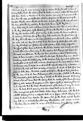
The wards may be made according to fancy. Whenever the key bit with its lever in turning the key touches the striking plate the tumblers are put in motion, the lower part of the lever touches a shoulder on the lower tumbler, and causes it to descend at the same time the upper part of the lever touches a projection in the under part of the parallel tumbler, raises the pin at the end projecting through the cap, and into the lever plate, thereby enabling the lever to be turned by the key bit.
These locks may be made with four or more tumblers, and two or more levers in the key. Description of the Drawing. No. 1. E. is the key bit, marked with a flat motion, in this motion the levers are placed. In drawing No. 2. are two of these keys both marked E. The front view of the key bit is the same as E. E. before mentioned. E. A. is such a lever of which two enter into one key bit E. P. Y. E. D. are two levers of which four enter into one key bit which are fastened by rivets, yet so as to be easily separable.
The effect of these levers is to make the tumblers descend and ascend parallel to each other. More levers may be thus applied but they are not required.
The wards are optional. The key bit here described is what I particularly claim to have invented. No. 1. A. B. P. is the lock. The lock I am now about describing works the contrary way to the common locks by a sort of lever, so constructed as to work with ease, an advantage it has over common locks. It however can be made so as to work the opposite way, or by a common bolt, but this will not lock so easily, it can also be made to lock from one side or both sides. The latch consists of two pieces, the front being marked A. the rear at. Z. its lever B. having a roller C. on pin at. D. D. is the spring the circulating parts fastened by a rivet at H. which prevents its turning round. I do not mean that the spring shall be exactly of this kind, for any spring will answer the purpose, as will appear by D. in drawing No. 2. nor is it requisite that the latch should consist of two pieces, it may be made as in the lock A. C. P. drawing No. 2. where latch and bolt are in one piece.
This arrangement of the bolt-latch I also claim to be used with the lock A. B. P. drawing 1. or as a separate lock as in figure A. C. P. drawing No. 2. which I shall now describe. The square hole for the knobs and the key hole are both in a vertical line, but any other position will answer as well. The lever has no roller C. as in A. B. P. drawing No. 1. the size of either
Page 5.
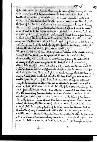
of the locks is immaterial, and they may be made of iron or any other material. a.b. is the bolt, b the lever. Whenever the bolt is turned, the hook of the tumbler M.B. marked 1 must stand in the corner marked 1 in the bolt which is a little higher than the other space. As soon as you turn the knob the part of the tumbler M.B. marked 2 will lay against the pin K, having thus room sufficient from the tumbler. The pin A of lever b must be made so as to rest in 2, but by no means on the point, because it would be in the way when pushing against the door. The spring D must have a fair bearing on the back of the lever b, so as to guide it. The tumbler M.B. is a common one and turns on a pin, v.D.D. is the spring of the tumbler v.D. The spring of the lever and holds the latch firmly, it is fastened by simply placing it behind the stud O which is filed somewhat obliquely.
The plate T rests on the four studs x, and is fastened to the studs v.K. by burrs. H.D. This latch can be opened at the same time with the key.
The wards they are optional. To return to the description of the lock A.B.P. drawing No. 1. B is a pin or guide to the bolt. O.G. is the bolt having an oblong hole in which it moves backwards & forwards on the pin d at B. It has a second hole in a different direction to receive the round stud from the lever marked 2. This is so high as to reach through the bolt. There is also a square stud on the bolt 2. A is the lever having an axis or spindle reaching from the plate of the lock to its cap, so as to afford sufficient play to the descending tumbler. This axis or spindle is perforated and filed above 2 is the stud moveable in the hole B. of the bolt 1, is the hole for the stud from the tumbler to work in. The two round dots are screw holes, P is the descending tumbler, having in 13 an elevation as exhibited in the drawing, and also a square stud 1 moveable in the hole 1 of the lever.
From the upper or lower side at D a hole is nearly bored through so as to admit the spring D.D. then a small clinch is driven in, and in the center a small hole bored fitting the pin of the spring which has likewise such a clinch. The spring is covered with a plate N. The spring must have at either end a small hook, and fitting the tumbler, the other the pin head. a.b. is a common tumbler working upwards. 2 is a hole for the square stud 2 on the bolt to move in at D. A hole is nearly bored through as before
Page 6.
242
9475X
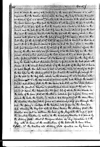
so as to admit the spring O.D. moving on the same pin. However it is not required that the tumblers should move this way, they may be made to ascend or descend. G.S. is a spindle, being denoted with three screws to the plate on which the lever moves. You then put the tumbler P with spring on the pin V, and then lever N on its pin G.S. so that the tumbler stick 1 works in its hole in the lever 1, and the hole B, in the bolt O.G. over the round stick 2 from the lever, then put the common tumbler M on the pin with the spring, which is then covered with plate U, so that the hole 2 may fit the square stick on the bolt, then fit the lever-plate S with its square hole to lever N, so that M.S. meet. M.D. is the female screw to fasten on V.S. the lever plate is marked with four principal holes, which by means of the parallel tumbler affords the security, the other two holes are for screwing it on the lever Y.Y. on the two screws. R is a roller sustaining the bolt-head. R.R. is a stand for the roller fastened with a screw. N is a wards. G. is a pin for the key which may be made without shoulders, it also is fastened to the lock plate with screws. K is the round board which is of the height of the key bit, it has in its entire length two holes, and is cut in at either end so deeply as to fit the two holes in the striking plate J, for J enters the cut high enough to fit the cut in the key hole which on the drawing No. 2 is marked with an arrow. T is the cap which is screwed on the lock through the round boards, and striking plate, by the two screws x.x. D.R. are two studs between which the parallel tumbler is screwed, and which support the axis on which it moves, this tumbler has two pins, like of which the one stands in the holes of the lever plate S. the other is intended for a false lever and secures the lock, the tumbler is marked Q.Q. designating at the same time the elevated shoulder, which forms a semicircle, and goes through the cap. The spring is rivetted to the tumbler, and prefers on the lever pin G.S. whenever the key bit with its lever touches the striking plate, the tumblers are put in motion, the lever of the key with the end 1 puts the parallel tumbler in motion 2. the descending tumbler 3 is moved by the striking plate. What I therefore claim as my invention is 1. the key with its lever. 2. the construction of the bolt with its lever & lever plate. 3. the tumblers and striking plate operated on by levers in
Page 7.
in the key. The bolt latch is one by their own.
N.B. the construction of the large latch is like that of the small one.
Witness
Jas. Goodman
Jas. Goodman
August. Pottymann
2/12 1857
Drawing
Published accounts: journal notice
Notice in the monthly list of patents
Journal of the Franklin Institute, new ser., vol. 17 (1836), p. 438 · View the page
163. Lever key and lock.-Augustus Prutzman, Philadelphia,
Published accounts: journal notice
Notice in the monthly list of patents, with remarks
Journal of the Franklin Institute, new ser., vol. 18 (1836), p. 319 · View the page
23. For an improvement in Locks and Keys denominated the Lever Lock and Key; Augustus Prutzmann, city of Philadelphia, March 4.
Remarks. A report upon this lock will be found at page 180; it having been submitted to the Committee on Science and the Arts. We cannot do better than refer to their report, as any attempt at description, without several drawings, would give a very imperfect idea of the construction of the locks. We have not looked enough into it to form a satisfactory opinion of its relative merits.
About this record
- Patentee
- DATAMP
- Date
- the Name and Date index of patents, DATAMP, USPTO records
- Invention
- DATAMP
- Listed in
- the Name and Date index of patents, DATAMP, USPTO records, Jim Shaw's X-patent list, the Journal of the Franklin Institute, Burke's List of Patents (1847)
- The Franklin Institute's journal spells the name differently.
- Burke's 1847 Patent Office list gives the same patent.