

Drawings and documents
National Archives restored drawings: drawing
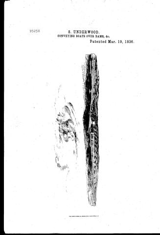
S. Underwood's Patent Drawing for a Means of Conveying Boats, Rafts, etc., Over Dams, Shoals, and Other Obstructions in Rivers

National Archives, Restored Patent Drawings (Record Group 241) · Full-size scan at the National Archives · Catalog record
Show the text on the drawing Hide (65 words)
Words on the drawing as machine-read by the National Archives; not checked. Useful mainly for searching.
GWAYS. / /AY." / clined Planes. / S o / 9.525.4 / conveying boats, rafts, ic over dams,stools, and other obstructions in Rivers / 95257 / Patented in 19 March 1830. / Vickland / Paterha office Jum / Made under the direction of the come / .B. can, corriagn,or cradle / in conformaly with ach of gall / C. vilrating railway. / Commission qt.
USPTO scan
The patent as scanned by the USPTO
-
 Page 1
-
 Page 2
-
 Page 3
-
 Page 4


U.S. Patent and Trademark Office · Google Patents
Show the transcription Hide (969 words)
Machine transcription (LightOnOCR) of the pages as scanned by the USPTO, most of them the handwritten copies made when the records were restored after the 1836 fire. Not checked; it can misread handwriting, so compare it with the scan.
Page 1.
9525X
S. UNDERWOOD.
CONVEYING BOATS OVER DAMS, &c.
Patented Mar. 19, 1836.

THE MORRIS PETERS CO., PHOTO-LITHO., WASHINGTON, D.C.
Page 2.
Pat. March 1836 9525X 489
Stephen Underwood of Bath St. of Grafton State of New Hampshire
Letters Patent
The Schedule referred to in these Letters Patent and making part of the same, containing a description in the words of the said Stephen Underwood himself, of his improvement in the Machine for conveying Boats, Rafts, etc., over Dams, shoals, and other obstructions in rivers.
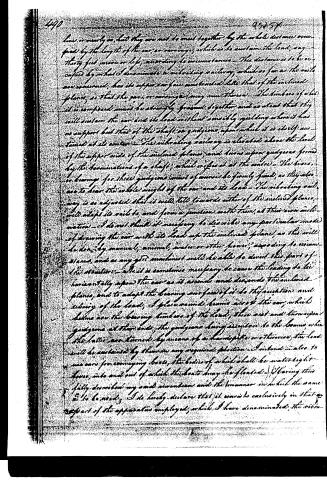
To all to whom it may concern, Be it known, that I Stephen Underwood of Bath in the County of Grafton and State of New Hampshire, have invented an improvement in the means of an apparatus for the conveying of Boats and Rafts and so forth over Dams, shoals, shoals or holes in rivers, and do hereby declare that the following is a full and exact description thereof. I construct two inclined planes, rail ways, which are to be made and fixed, in the manner of the well-known marine railways, for hauling rafts out of water for a space. I also construct a car, carriage, or cradle, which is to run upon trucks, wheels or rollers in a manner also similar to those used for moving rafts to be drawn upon marine railways. One of the before-mentioned railways is to be constructed and fixed above the dam or other obstruction its lower end being up stream, and so far below the surface of the water as may be required to float the raft or other load, on to the car, or carriage which is then to stand thereon. The other railway is to be below the dam and so forth inclining downstream and in all other respects constructed like that first named. The length of these railways must vary so as to adapt them to the situation in which they are to be placed, and this will be governed by the depth of the water, the height of the obstruction, and the inclination which must be given to cause the power applied to be sufficient to raise the load. Should there be no ascending traffic, the inclination of the lower may exceed that of the upper railway. The upper ends of these railways are to be on the same horizontal
Page 3.
line or nearly so, but they are not to meet together by the whole distance occupied by the length of the car or carriage, which is to sustain the load, any thirty feet more or less, according to circumstances. This distance is to be occupied by what I denominate a vibrating railway, which so far as the rails are concerned, has its upper surface constructed like that of the inclined plane, so that the cars or carriages may run thereon. The timbers of which it is composed must be strongly fastened together and so stout that they will sustain the car and its load without sensibly yielding when it has no support but that of the shaft or guidons, upon which it is itself sustained at its center. The vibrating railway is elevated above the level of the upper side of the inclined plane, and bears upon guidons formed by the terminations of a shaft, which arises at the center. The boxes, or bearings for these guidons must of course be firmly fixed, as they also are to bear the whole weight of the car and its load. The vibrating railway is so adjusted that it will tilt towards either of the inclined planes, will adapt its rails to and form a junction with them, at their own inclination. I do not think it necessary to describe any particular mode of drawing the car with its load up the inclined plane, as this will be done by manual, animal, water or other power, according to circumstances, and as any good machinist will be able to devise this part of the structure. Also it is sometimes necessary to cause the leading to lie horizontally upon the car as it ascends and descends the inclined plane, and to adapt the bearing surfaces of it to the curvature and riding of the load, I place round beams across the car, which below are the bearing timbers of the load, these are and turn upon guidons at their ends, the guidons being attached to the beams, when the latter are turned by means of a handspoke or otherwise, the load will be sustained by them in any required position. I intend also to use cars for conveying boats, the bodies of which shall be water-tight boxes, into and out of which the boats may be floated. Having thus fully described my said invention and the manner in which the same is to be used, I do hereby declare that it consists exclusively in that part of the apparatus employed, which I have denominated the vibratory
Page 4.
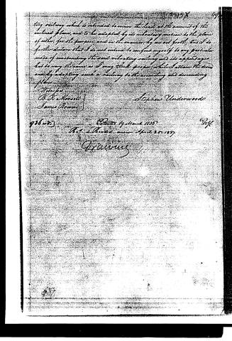
ting railway which is intended to receive the loads at the summit of the inclined plane, and to be adapted, by its vibrating motion to the plane of either, for the purpose, and in the manner, by me set forth; and I do further declare that I do not intend to confine myself to any particular mode of constructing the said vibrating railway and its appendages but to vary the same as I may think proper while I attain the said end by adapting such a railway to the ascending and descending planes.
Witness
B. H. Howells
James Brown
Stephen Underwood
Patented 19 March 1836
Re-issued April 25, 1837
Drawings
Published accounts: journal notice
Notice in the monthly list of patents
Journal of the Franklin Institute, new ser., vol. 17 (1836), p. 439 · View the page
217. Boats, passing over dams. Stephen Underwood, Bath, N. H.
Published accounts: journal notice
Notice in the monthly list of patents, with remarks
Journal of the Franklin Institute, new ser., vol. 18 (1836), p. 392 · View the page
77. For a mode of Conveying rafts, boats, &c., over dams and shoals; Stephen Underwood, Bath, Grafton county, New Hampshire, March 19.
Remarks. Two inclined, plane rail-ways are to be erected, one on each side of the dam, or other obstruction, over which a boat, &c., is to be carried; these are to extend into the stream, so that the load can be floated on to a car, constructed to run upon the planes. The planes are to terminate, at their upper ends, at the distance of from thirty to sixty feet from each other, or equal to that of the car upon which the boat or raft is to be carried. This space is occupied by a vibrating rail-way or bridge, which tilts on a centre, and will form a continuous plane with either of the sections accordingly as it is tilted towards the one or the other. A windlass, turned by water, or other power, receives a rope, or chain, by which the car can be raised, or lowered, upon the planes. When a load is to ascend, the bridge is tilted towards the plane up which it is to be drawn, and it is hauled upon it; the bridge is then tilted towards the descending plane, and the load is lowered into the water. There is a contrivance on the car, by an arrangement of eccentric rollers, by which the level of the load can be changed, so that it shall stand horizontally in ascending and descending. The claim is confined exclusively "to that part of the apparatus employed, which is denominated the vibrating rail-way, which is intended to receive the load at the summit of the inclined plane, and to be adapted by its vibrating motion to the plane of either, for the purpose, and in the manner set forth."
About this record
- Patentee
- DATAMP
- Date
- the Name and Date index of patents, DATAMP, USPTO records
- Invention
- DATAMP
- Listed in
- the Name and Date index of patents, DATAMP, USPTO records, Jim Shaw's X-patent list, the Journal of the Franklin Institute, Burke's List of Patents (1847)
- Burke's 1847 Patent Office list gives the same patent.